
Rotation sensor unit

Active Publication Date: 2009-10-01
NTN CORP
View PDF7 Cites 9 Cited by
  • Summary
  • Abstract
  • Description
  • Claims
  • Application Information

AI Technical Summary

Benefits of technology

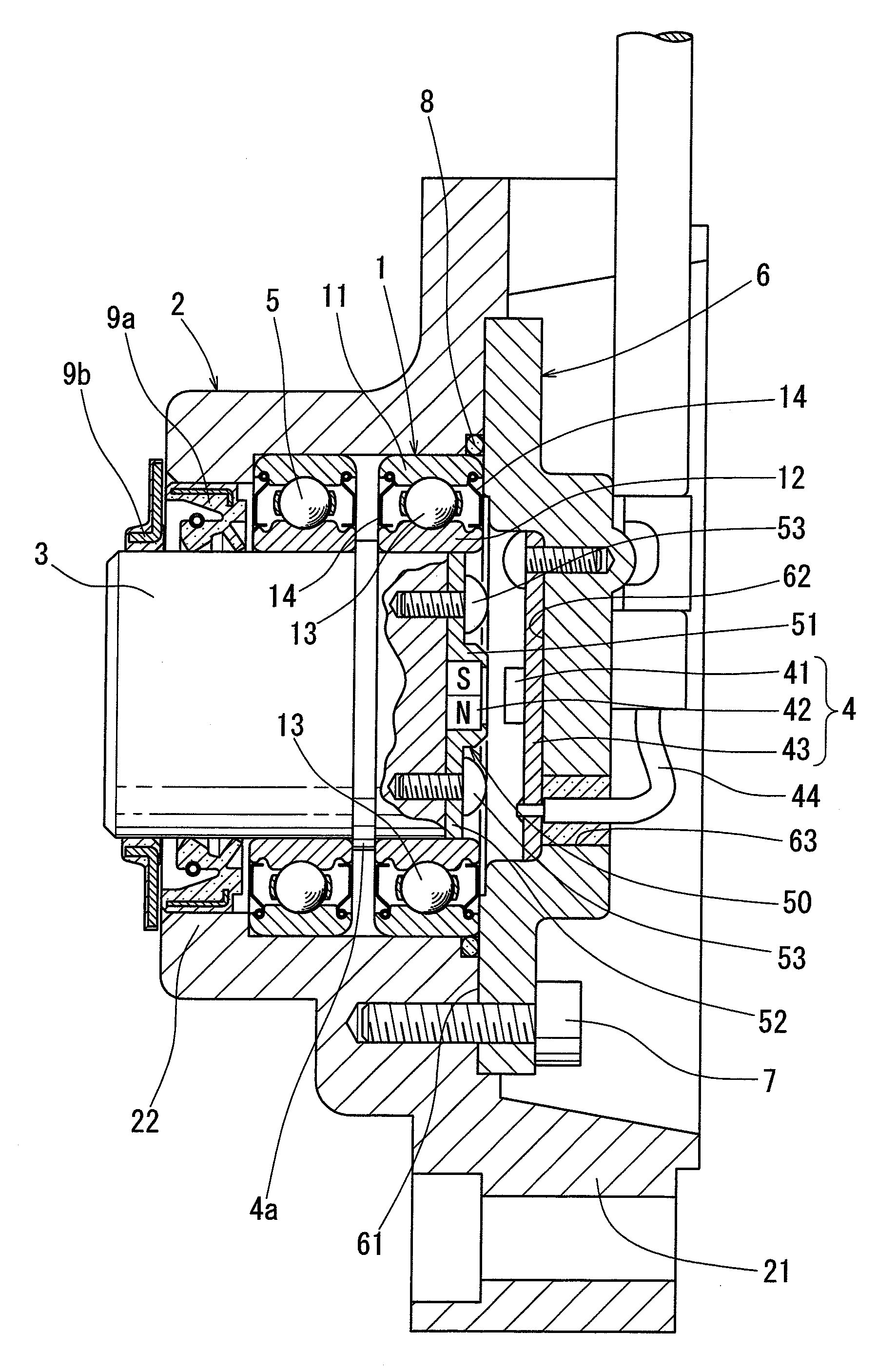
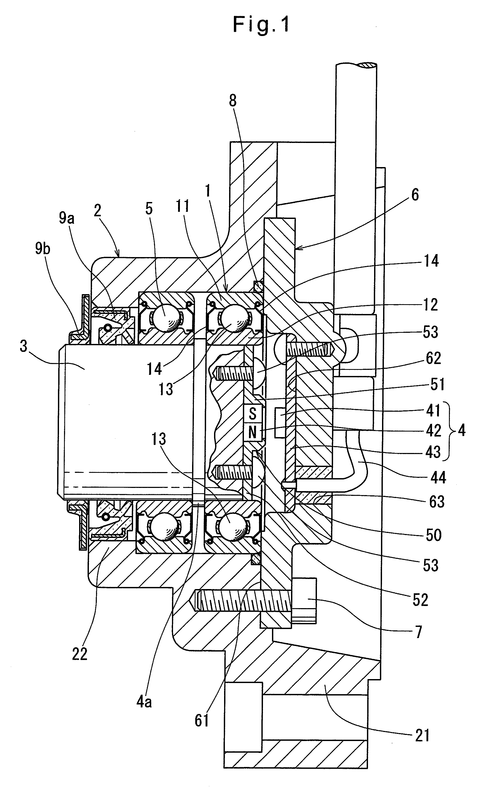
[0010]Flux from the encoder to the magnetism detection element is not caught by the holder. Therefore in the rotation sensor unit according to the first arrangement, positioning the encoder radially with the holder does not adversely affect the magnetic field formed by the encoder.
[0012]The holder can be fixed to the shaft by screwing. The screwed portion and the screw members are provided between the retaining portion that retains the encoder and the end of the inner diameter surface of the inner race. Using non-magnetic materials for the screwed portion and the screw members, flux from the encoder to the magnetism detection element is not caught by the screwed portion or the screw member. Therefore in the rotation sensor unit according to the third arrangement, screwing the holder to the shaft does not adversely affect the magnetic field formed by the encoder.
[0016]Preload to a rolling bearing increases the rigidity of the roller bearing, and prevents run-out of the shaft. Since the encoder is provided and rotated coaxially and integrally with the shaft in which run-out is prevented, relative displacement between the magnetism detection element and the encoder is prevented. Further, the space between the lid and the end surface of the shaft on the first side is surrounded by the lid and the outer race. This makes it possible to define a magnetically shielded space by using magnetic materials for the lid, the shaft and the outer race. The magnetism detection element fixed to the lid on the side facing to the end of the shaft on the first side can be provided in the magnetically shielded space. Thus in the invention according to the fourth arrangement, the magnetism detection element can be shielded from external magnetic field without recourse to an additional magnetically shielded cover or the housing. This makes it possible to reduce the number of parts of the sensor unit and make the unit compact.
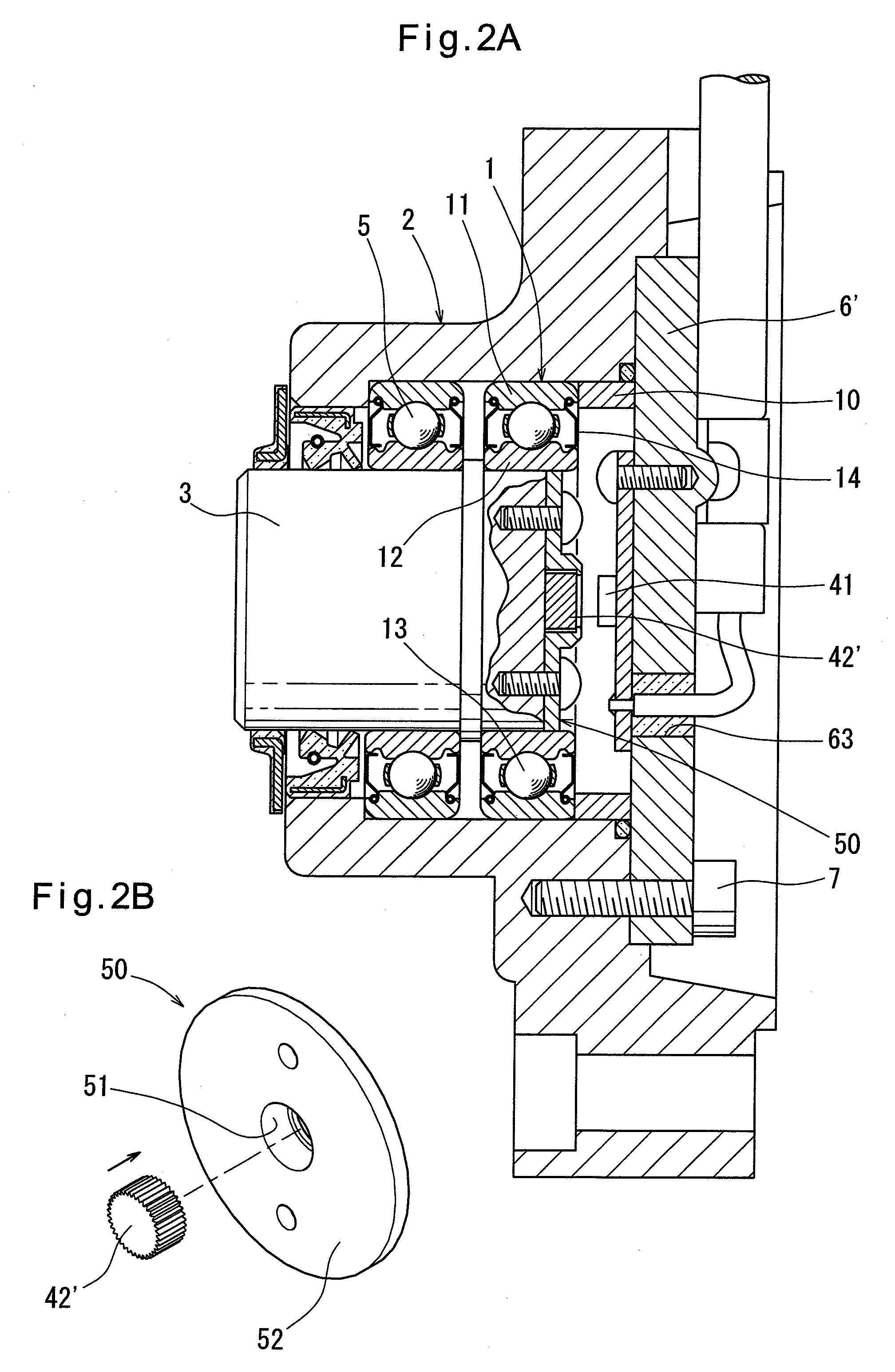
[0018]Simply by pressing the encoder into the retaining portion of the holder in the axial direction, the retainer can be radially held in position. If this retaining portion is non-magnetic, the retaining portion can be made of a synthetic resin. If the retaining portion is made of a synthetic resin, the holder can be formed by integral injection molding. But in this case, interference between the encoder and the retainer decreases with time because of creep of the synthetic resin. Since the shaft and the encoder are required to rotate integrally in a magnetic encoder, the encoder can be bonded to the retainer as one counter-measure for the above-mentioned creep. Instead of this bonding, protrusions and recesses can be formed on the outer diameter surface of the encoder so that they bite the inner diameter surface of the retainer, thereby preventing the encoder from rotating when the encoder is pressed in. Thus in the rotation sensor unit according to the fifth arrangement, the encoder is retained by the retaining portion and prevented from rotating by creep when the encoder is pressed in the retaining portion made of a synthetic resin. This makes the assembly process simpler compared to bonding with adhesive.
[0020]In the rotation sensor unit according to the sixth arrangement, the encoder is protruded and recessed symmetrically with respect to the axis of the encoder, radial distribution of flux from the encoder is symmetrical with respect to the axis of the encoder, which prevents negative influence to the detection accuracy caused by protruded and recessed configuration.

Problems solved by technology

Also, the material of the shaft of the rotation sensor unit of JP 3086563 is limited to non-magnetic materials.

Method used


Image

  • Rotation sensor unit
  • Rotation sensor unit
  • Rotation sensor unit

Examples


embodiment 1

[0027 is protected from external forces by a protection cover, or used under such a working condition that the housing 2 will not be broken by external force. The housing 2 is therefore formed by integral injection molding of a resin for weight saving and formability rather than for strength. But the housing 2 may be made of aluminum, instead.

[0028]The shaft 3, the outer race 11 and an inner race 12 of the rolling bearing 1, and rolling elements 13 provided between the races 11 and 12 are made of soft magnetic materials. Ferric soft magnetic materials may be used for these members, and paramagnetic materials are preferred to prevent members such as the shaft 3 from being magnetized.

[0029]Each seal 14 of the first rolling bearing 1 has a shield plate portion extending from the attachment end that is pressed into a seal groove of the outer race 11 to the opposite end. The shield plate portion of each seal 14 is made of a soft magnetic material. Flux of the external magnetic field ther...

embodiment 2

[0064]The above-mentioned protrusions and recesses are knurls that are symmetric with respect to the axis of the encoder. In Embodiment 2, since the knurls are symmetric relative to the axis of the encoder, radial distribution of flux from the encoder 42′ can also be formed symmetrically relative to the axis of the encoder. This prevents negative influence on the detection accuracy caused by protruded and recessed configuration of the encoder 42′. The protrusions and recesses are not limited to knurls and they can be of any convenient forms, e.g. grid-like cuts, considering factors such as the above-mentioned locking effect and uniform flux distribution.

[0065]The encoder 42′ should be a plastic magnet formed by integral injection molding. In Embodiment 2, the above-mentioned protrusions and recesses are formed simultaneously when the encoder 42′ is molded, and there is no need for forming the protrusions and recesses in an extra post-processing. The plastic magnet is made of a plast...


PUM


Abstract

A rotation sensor unit includes an encoder, a holder radially positioning the encoder, and a rolling bearing having an inner race. The rolling bearing is fitted around the shaft so that one end of the inner diameter surface of the inner race protrudes from the end of the outer diameter surface of the shaft. The holder has a screwed portion fitted in the inner race, positioning the encoder coaxially with the shaft. The holder is non-magnetic, having a retaining portion in which the encoder is axially pressed. The encoder is a plastic magnet, with protrusions and recesses formed integrally on its outer diameter surface and biting the inner diameter surface of the retaining portion to prevent the encoder from rotating. With the holder screwed to the shaft, the encoder is disposed between the magnetism detection element and the one end of the shaft.

Description

BACKGROUND OF THE INVENTION[0001]This invention relates to a rotation sensor unit that detects rotation of a shaft with a magnetic encoder.[0002]As a rotation sensor unit of this type, a rotation sensor unit comprising a rolling bearing having an outer race, a housing in which the outer race of the rolling bearing is fitted, a shaft supported by the rolling bearing and a magnetic encoder for detecting rotation of the shaft is widely used. The encoder of the magnetic encoder should be a magnet having north and south poles provided alternately in the circumferential direction around the axis of the shaft. The encoder is provided coaxially with the shaft so that it rotates integrally with the shaft. The magnetism detection element of the magnetic encoder is provided so that it axially faces to the encoder. The area of each surface of the encoder and the magnetism detection element facing axially with each other is much smaller than the area of the end surface of the shaft, and therefor...

Claims


Application Information

Patent Timeline
IPC IPC(8): G01B7/30
CPCG01D5/145F16C41/007G01P3/487G01P3/443
Inventor ITOMI, SHOJI
Owner NTN CORP
Learn More