Image processing device, computer-readable storage medium, and electronic apparatus
- Summary
- Abstract
- Description
- Claims
- Application Information
AI Technical Summary
Benefits of technology
Problems solved by technology
Method used
Image

Examples
first embodiment
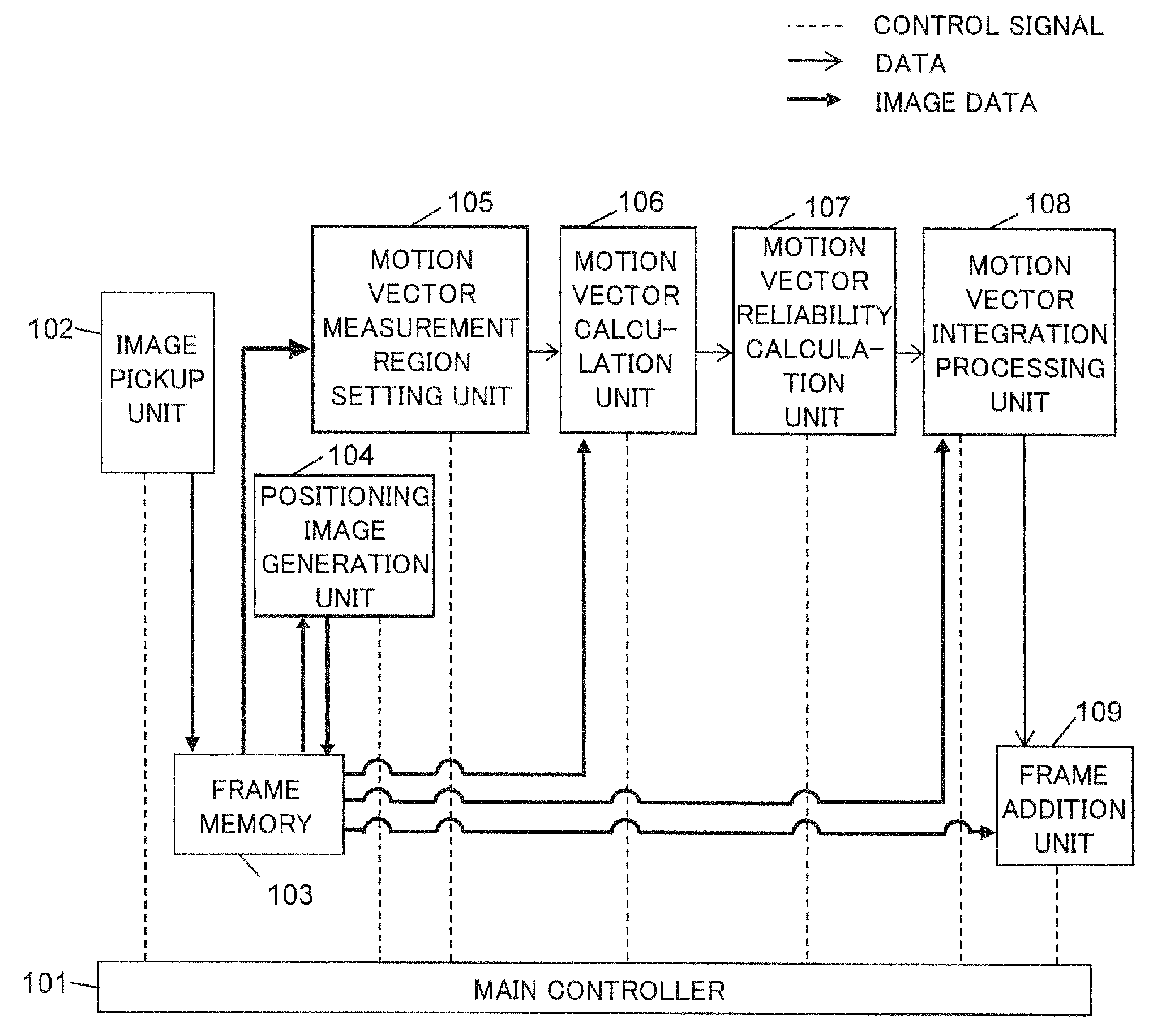
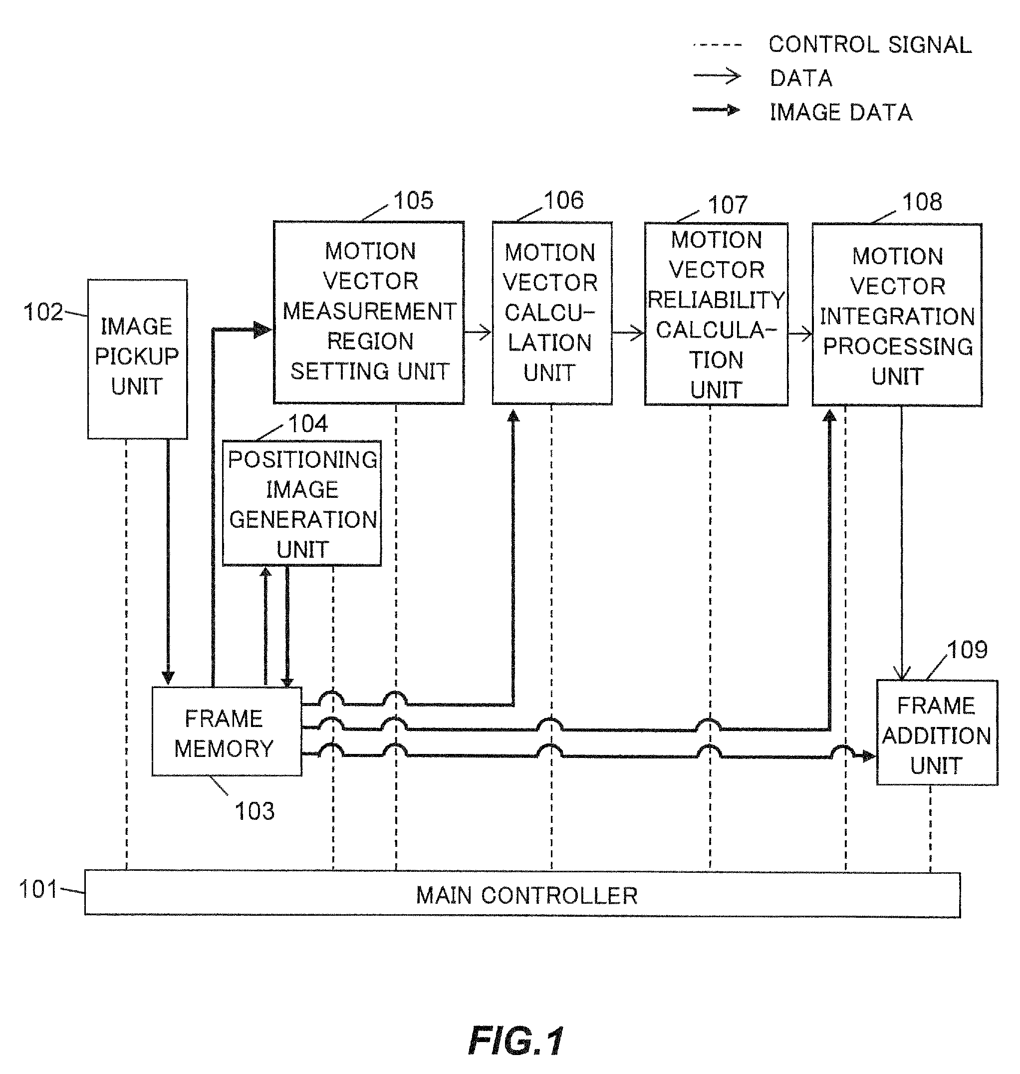
[0029]FIG. 1 is a block diagram showing the constitution of an image processing device for performing electronic blur correction according to a first embodiment. In the figure, dotted lines denote control signals, thin lines denote the flow of data such as reliability values and positional displacement amounts, and thick lines denote the flow of image data. The image processing device according to this embodiment is installed in an electronic apparatus. The electronic apparatus is a device that depends on an electric current or an electromagnetic field in order to work correctly, and may be a device such as an electronic calculator, a digital camera, a digital video camera, or an endoscope, for example.
[0030]A main controller 101 is a processor for performing operation control of the entire device. The main controller 101 performs command generation and status management in relation to respective processing blocks.
[0031]Multiple image frames captured by an image pickup unit 102 are ...
second embodiment
[0072]FIG. 8 is a block diagram showing the constitution of an image processing device for performing electronic blur correction, according to a second embodiment. Identical constitutional elements to the constitutional elements of the image processing device according to the first embodiment, shown in FIG. 1, have been allocated identical reference symbols, and detailed description thereof has been omitted.
[0073]The image processing device according to this embodiment differs from the image processing device according to the first embodiment shown in FIG. 1 in that both the pixel precision motion vector and the sub-pixel precision motion vector are calculated in a motion vector calculation unit 106A (to be referred to hereafter simply as a calculation unit 106A). Hence, in the calculation unit 106A, the pixel precision motion vector and the sub-pixel precision motion vector are determined on the basis of the positioning image (reference frame), the positioning image (subject frame)...
third embodiment
[0081]In the first and second embodiments described above, examples of frame addition were illustrated, but moving image blur correction may be performed by performing image shifting on the subject frame relative to the reference frame on the basis of a motion vector representative value.
[0082]FIG. 10 is a block diagram showing the constitution of an image processing device according to a third embodiment. The image processing device according to the third embodiment differs from the image processing device according to the first embodiment shown in FIG. 1 in having a frame motion correction unit 110 (to be referred to hereafter simply as a correction unit 110) instead of the frame addition unit 109.
[0083]The correction unit 110 performs processing to correct the subject frame so as to reduce blur relative to the reference frame on the basis of the representative positional displacement amount determined by the processing unit 108. Corrected data are transferred to a display device,...
PUM
 Abstract
Description
Claims
Application Information
 - R&D Engineer
- R&D Manager
- IP Professional
- Industry Leading Data Capabilities
- Powerful AI technology
- Patent DNA Extraction
Browse by: Latest US Patents, China's latest patents, Technical Efficacy Thesaurus, Application Domain, Technology Topic.
© 2024 PatSnap. All rights reserved.Legal|Privacy policy|Modern Slavery Act Transparency Statement|Sitemap