Contact Displacement Meter
- Summary
- Abstract
- Description
- Claims
- Application Information
AI Technical Summary
Benefits of technology
Problems solved by technology
Method used
Image
Examples
first embodiment
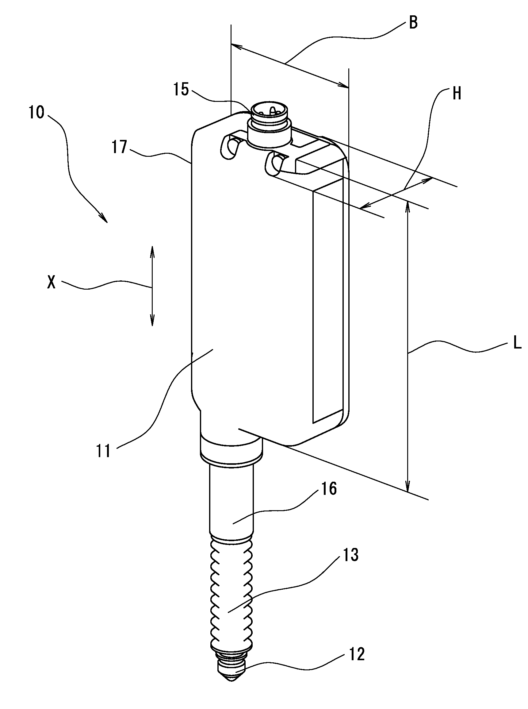
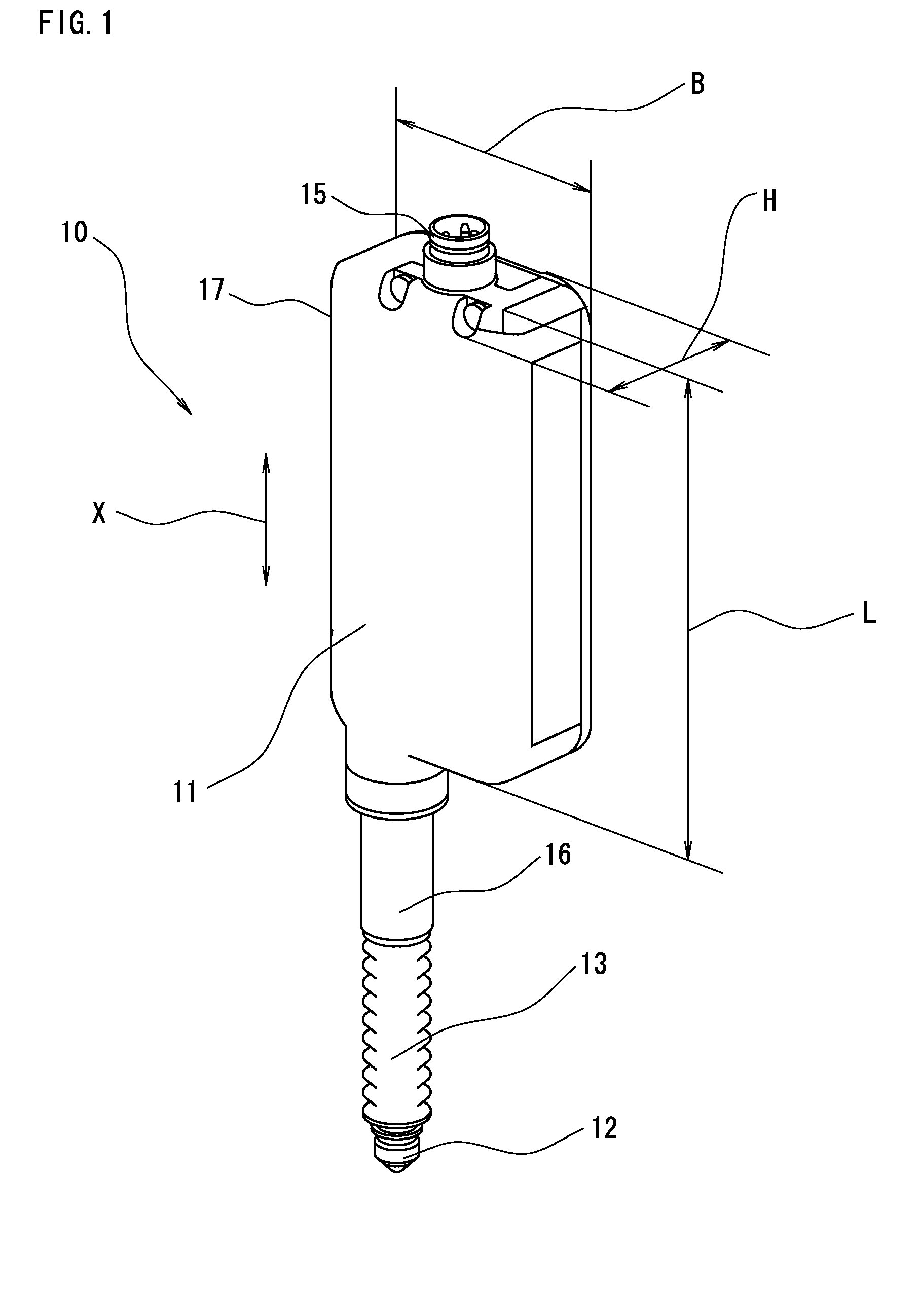
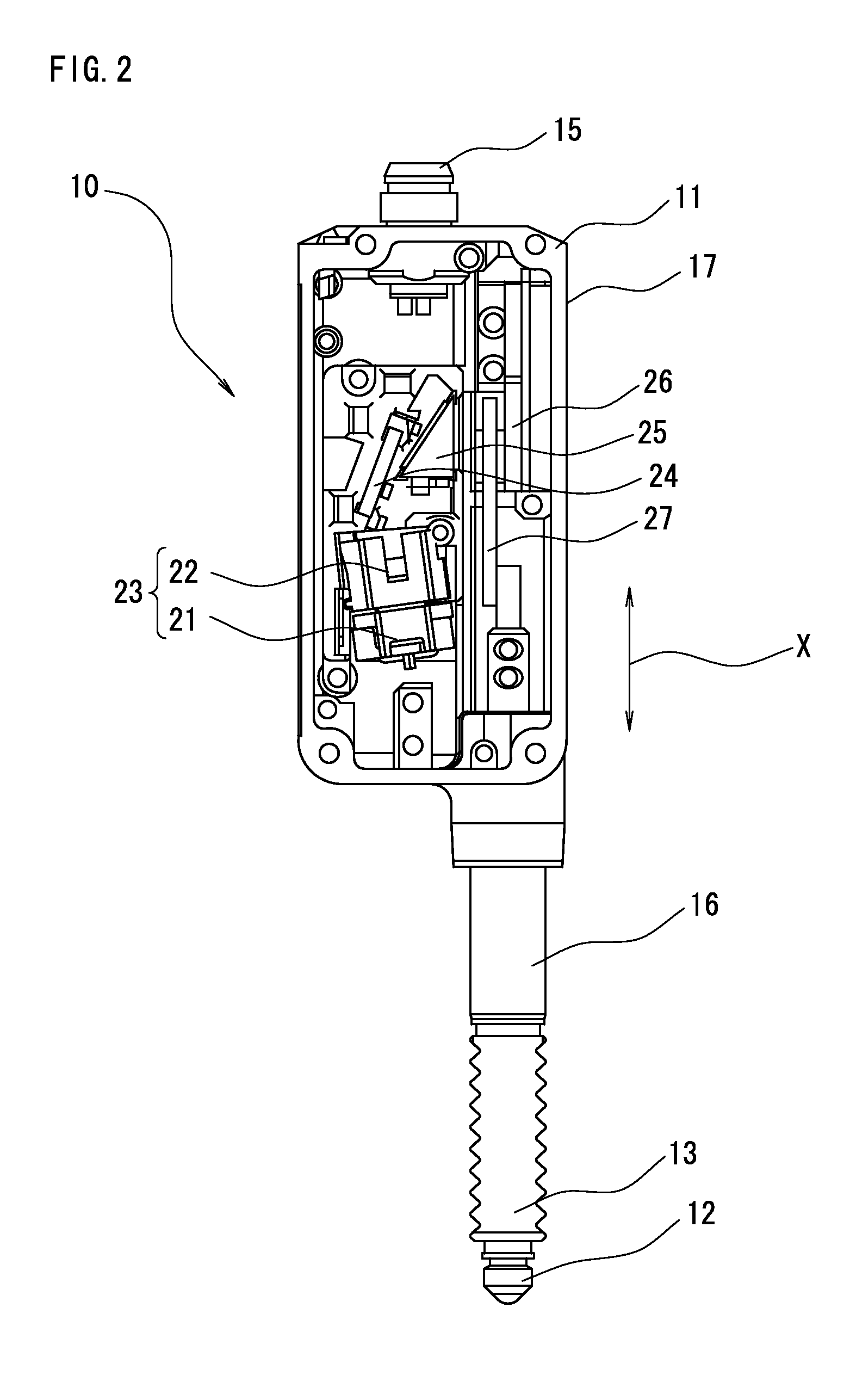
[0037]FIG. 1 is a perspective view showing an outer appearance of a contact displacement meter according to First Embodiment of the present invention. A contact displacement meter 10 according to First Embodiment includes, in the interior of a housing 11, a contact 12 relatively movable in one direction (X direction shown in FIG. 1) with the housing 11, and measures the relative displacement in the X direction of the contact 12 with respect to the housing 11. An accordion cover 13 is arranged between the contact 12 and the housing 11 to prevent dust, dirt, and the like from entering the moving portion. The housing 11 has a substantially rectangular solid shape, which size L×W×H is about 60 mm×30 mm×15 mm.
[0038]A substantially cylindrical contact holder 16 is formed on the outer side of the housing 11 along the X direction from a surface orthogonal to the X direction of the housing 11. As shown in FIG. 1, the contact holder 16 is formed at a position deviated towards a first side sur...
second embodiment
[0065]FIG. 7 is a plan view showing an arrangement near the optical mechanism of the contact displacement meter 10 according to Second Embodiment of the present invention. Same reference numerals are denoted for the same components as FIGS. 1 to 3, and the detailed description thereof will be omitted.
[0066]As shown in FIG. 7, the light emitting element 21 and the lens 22 are incorporated in an integrated element holder 23 in a substantially square shape, which element holder 23 has a rotational mechanism for rotating with the corner closest to the prism 25 as the center of rotation 28 with respect to the housing 11. Therefore, when the element holder 23 rotates with the center of rotation 28 as the center, the position, and the like of the light exit from the prism 25 can be finely tuned.
[0067]FIGS. 8A and 8B are schematic views for comparing the rotational moment of the element holder 23. FIG. 8A shows a case where an intersection 28′ of the diagonal lines, which is substantially t...
third embodiment
[0075]FIG. 10 is a perspective view including the connector portion 15 of the contact displacement meter 10 according to Third Embodiment of the present invention. The housing 11 of the contact displacement meter 10 is normally sealed such that air inside does not leak outside. In particular, the accordion cover 13 is arranged to obtain an air-tight state to support a smooth movement with respect to the inserting portion of the moving contact 12. Therefore, in a case where the contact 12 moves, the air inside the housing 11 acts as a resistance and an accurate displacement may not be measured.
[0076]As shown in FIG. 10, a hole 92 passed through into the housing 11 is formed in the connector portion 15 connected with the external wiring in addition to a plurality of connection pins 91, 91, . . . for connection. When the contact 12 moves, the air inside the housing 11 is discharged to the outside from the connector portion 15 via the hole 92 or outside air is taken in.
[0077]Therefore, ...
PUM
 Abstract
Description
Claims
Application Information
 - R&D
- Intellectual Property
- Life Sciences
- Materials
- Tech Scout
- Unparalleled Data Quality
- Higher Quality Content
- 60% Fewer Hallucinations
Browse by: Latest US Patents, China's latest patents, Technical Efficacy Thesaurus, Application Domain, Technology Topic, Popular Technical Reports.
© 2025 PatSnap. All rights reserved.Legal|Privacy policy|Modern Slavery Act Transparency Statement|Sitemap|About US| Contact US: help@patsnap.com


