

Multiferroic layer, structure including the layer, and methods of forming the layer and the structure
a multi-ferroic layer and structure technology, applied in the field of multi-ferroic layer, a structure including the layer, can solve the problems of low ferroelectric transition temperature tc and remnant polarization value psub>r /sub> to be applied to actual elements, and the electric or magnetic properties of epitaxially stabilized not shown, so as to achieve enhanced multi-ferroic properties
- Summary
- Abstract
- Description
- Claims
- Application Information
AI Technical Summary
Benefits of technology
Problems solved by technology
Method used
Image

Examples
example 1
Formation of TbMnO3 Layer
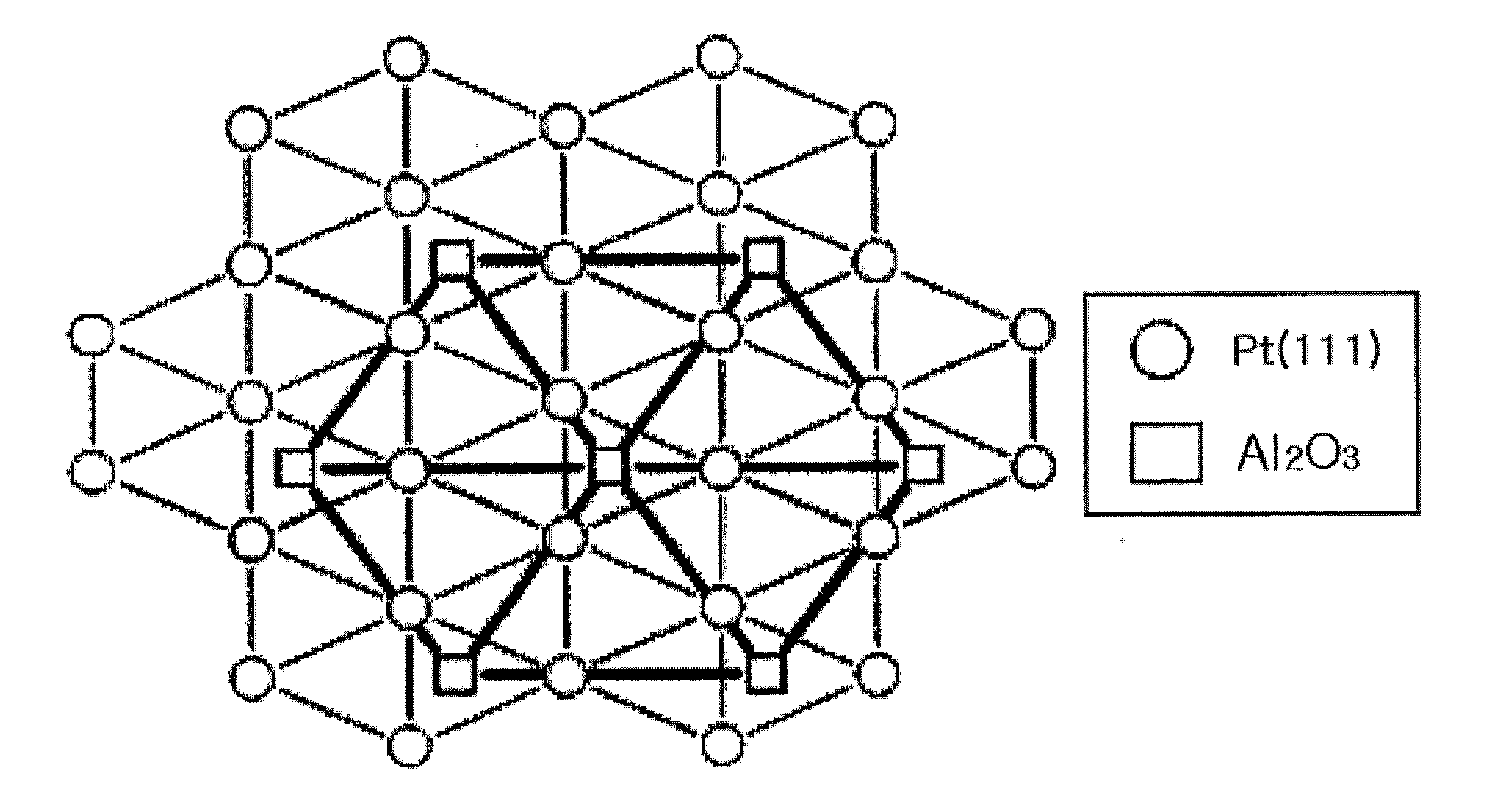
[0042]The TbMnO3 layer was formed on a sapphire substrate [Al2O3 (001)] which has a hexagonal surface structure, using pulsed laser deposition method. In particular, the TbMnO3 powder was annealed at 1350° C. for 24 hours, pressurized by hydrostatic pressure of 140 psi and finally sintered to form a TbMnO3 target. Then, the plasma was formed by illuminating the laser pulse from the KrF excimer laser on said target, and using said plasma, a TbMnO3 layer was formed on the sapphire substrate. During the process, the 4 pulse / sec repetition rate of laser with 0.4 W / s fluences were used. Also, while the layer was being formed, the substrate temperature was 850° C.˜900° C., oxygen pressure was 30˜100 mTorr, and base vacuum pressure was 10−6 Torr. A 50 nm thick TbMnO3 layer was obtained by depositing the TbMnO3 material for 20 minutes under such condition.
[0043]The XRD (X-ray diffraction) result of TbMnO3 layer formed in example 1 is shown in FIG. 7. FIG. 7 is an XR...
example 2
Formation of Structure
[0044]By using Dc-magnetron sputter, the 20 nm thick Pt layer was formed on sapphire (001) substrate. Then, on the Pt layer, the TbMnO3 layer was formed as shown in example 1. The XRD results analyzing the multiferroic structure formed as above are shown in the following FIGS. 8˜11. FIGS. 8˜11 are scan graphs illustrating the XRD results analyzing the structure formed by example 2. In particular, FIG. 8 is a XRD θ-2θ scan graph of TbMnO3 layer formed on a Pt coated sapphire substrate, FIG. 9 is an XRD Φ scan graph of TbMnO3 layer, FIG. 10 is an XRD Φ scan graph of Pt layer, and FIG. 11 is an XRD Φ scan graph of the sapphire substrate.
[0045]In FIG. 8, the hexagonal TbMnO3 peaks of 002, 004 are shown at 15.5° and 31°. Thus, it can be known that the TbMnO3 layer has hexagonal crystalline structure. Also, as shown in FIG. 8, the peak at 39° indicates the 111 oriented grown Pt layer and the peak at 42° indicates the sapphire substrate. FIGS. 9˜11 show the XRD scan r...
example 3
Formation of Capacitor
[0046]A capacitor is formed by forming an Au layer on top of the multiferroic structure formed in example 2. In particular, a capacitor comprising a Pt layer as bottom electrode, TbMnO3 layer which has hexagonal crystalline structure as a dielectric layer, and an Au layer as top electrode, is formed.
[0047]The multiferroic properties against the TbMnO3 layer in the capacitor formed as above were measured. In particular, by using a T-F analyzer, the ferroelectric polarization value of the TbMnO3 layer was measured at various frequencies and temperature. The results are shown in FIGS. 12˜14. More particularly, FIG. 12 is a graph illustrating the function between the polarization value of the TbMnO3 layer included in the capacitor and electric field at a frequency of 2 kHz and a temperature of 50 K, FIG. 13 is a graph illustrating the function between the polarization value of the TbMnO3 layer included in the capacitor and electric field at a temperature of 80 K, a...
PUM
| Property | Measurement | Unit |
|---|---|---|
| Transition temperature | aaaaa | aaaaa |
| Transition temperature | aaaaa | aaaaa |
| Transition temperature | aaaaa | aaaaa |
Abstract
Description
Claims
Application Information