Relieved-channel, bonded heat exchanger

a heat exchanger and relief channel technology, applied in the field of heat transfer, can solve the problems of requiring cooling of electrical and electronic devices that consume electricity, requiring one particular demanding environment for spacecraft, and requiring substantial loads of any structure during launch, and achieves excellent structural strength and structural stiffness, the effect of reducing the temperature differential and reducing the load

Inactive Publication Date: 2009-10-08
UTAH STATE UNIVERSITY
View PDF7 Cites 15 Cited by
  • Summary
  • Abstract
  • Description
  • Claims
  • Application Information

AI Technical Summary

Benefits of technology

[0012]In one embodiment of an apparatus and method in accordance with the invention, a panel assembly for exchanging heat with an ambient environment maintains minimal temperature differential by virtue of operation as a heat pipe apparatus. Panels of a composite material having excellent structural strength and structural stiffness but comparatively modest thermal conductivity are machined as mirror images of one another. Two orthogonal arrays of parallel channels are machined in the faces of two panels, each intersection of channels forming and bounded by pedestals having a lower, broader base with a narrower upper portion extending from a shoulder of the base portion of the pedestals. The pedestals, in turn, form the bounds of the channels, each having a deeper narrower aspect extending along the bases of all the pedestals. Channels have a broader aspect extending along near the tops of the pedestals. The tops of the pedestals may be treated with a bonding material and bonded together as panels are placed together as mirror images of one another to make contact at each pedestal. An extremely strong, rigid structure results, capable of surviving launch loads, while still providing excellent heat pipe characteristics. Transport of liquids occurs through the bottoms of narrower portions of channels while vapor returns by way of the broader portions of channels available near the tops of all the pedestals.

Problems solved by technology

Meanwhile, electrical and electronic devices that consume electricity likewise require cooling.
One particularly demanding environment occurs with spacecraft.
Meanwhile, the loads required of any structure during launch may be substantial.
Thus, the combination of light weight and high strength is difficult to achieve.

Method used


Image

  • Relieved-channel, bonded heat exchanger
  • Relieved-channel, bonded heat exchanger
  • Relieved-channel, bonded heat exchanger

Examples


Embodiment Construction

[0029]It will be readily understood that the components of the present invention, as generally described and illustrated in the drawings herein, could be arranged and designed in a wide variety of different configurations. Thus, the following more detailed description of the embodiments of the system and method of the present invention, as represented in the drawings, is not intended to limit the scope of the invention, as claimed, but is merely representative of various embodiments of the invention. The illustrated embodiments of the invention will be best understood by reference to the drawings, wherein like parts are designated by like numerals throughout.

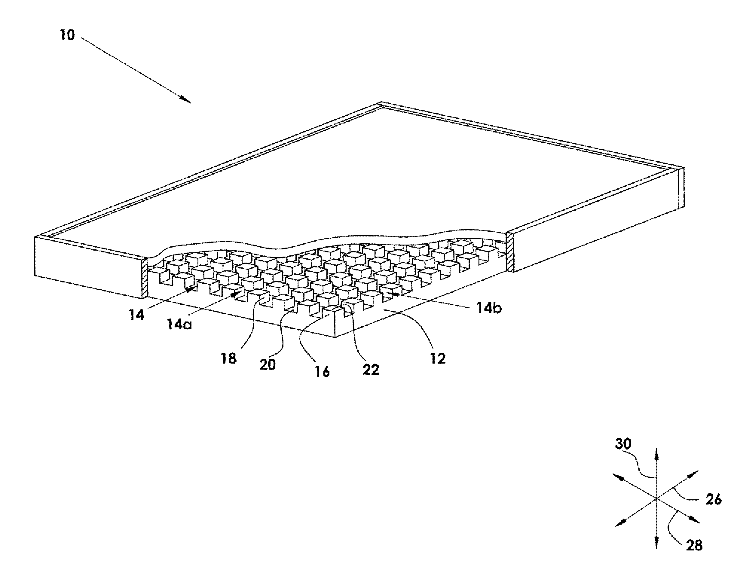
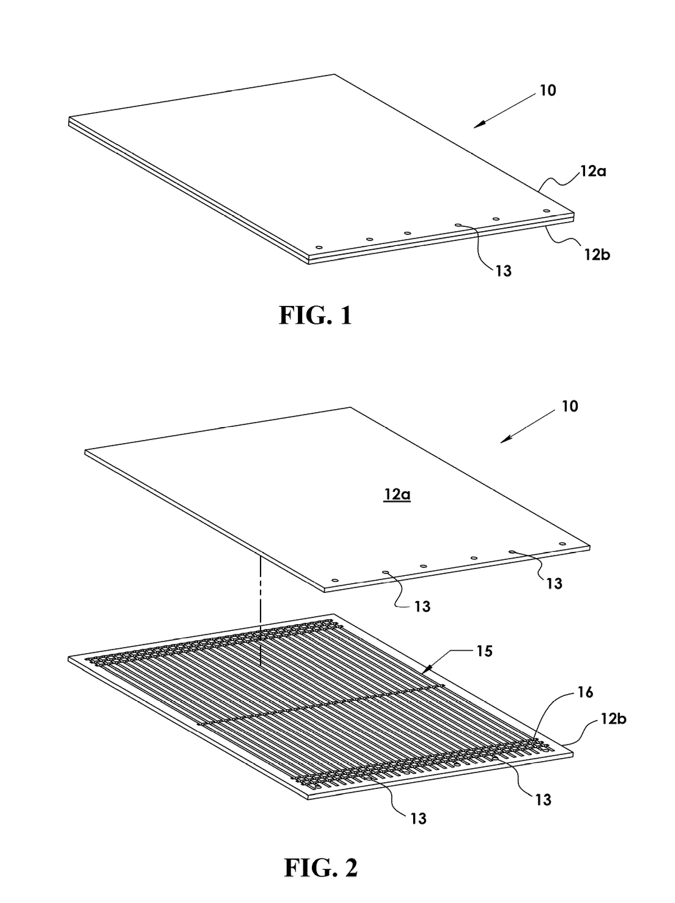
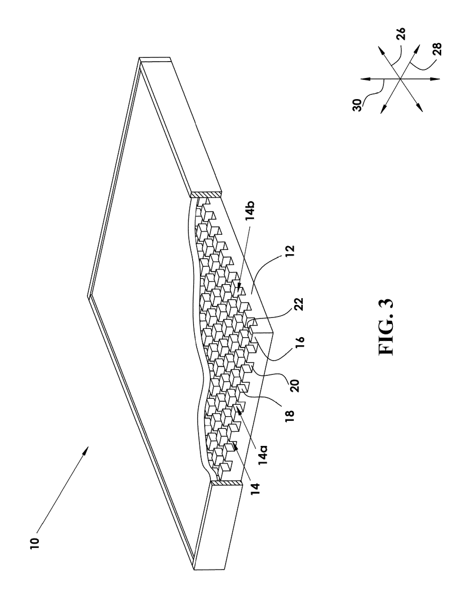
[0030]Referring to FIG. 1, and to FIGS. 1-5 generally, a system 10 in accordance with the invention may include panels 12, such as the illustrated panels 12a, 12b bonded to one another to form a closed panel assembly 10 having enclosed channels 14 therebetween. In certain embodiments, a pair of panels 12 may be formed and subseq...


PUM

PropertyMeasurementUnit
aspect ratioaaaaaaaaaa
thicknessaaaaaaaaaa

Abstract

A panel assembly for exchanging heat with an ambient environment maintains minimal temperature differential by virtue of operation as a heat pipe apparatus. Panels of a composite material having excellent structural strength and structural stiffness but comparatively modest thermal conductivity are machined as mirror images of one another. Two orthogonal arrays of parallel channels are machined in the faces of two panels, each intersection of channels forming and bounded by pedestals having a lower, broader base with a narrower upper portion extending from a shoulder of the base portion of the pedestals. The pedestals, in turn, form the bounds of the channels, each having a deeper and a narrower aspect extending along the bases of all the pedestals. Channels have a broader aspect extending along near the tops of the pedestals.

Description

RELATED APPLICATIONS[0001]This application claims the benefit of co-pending U.S. Provisional Patent Application Ser. No. 61 / 042,205, filed on Apr. 3, 2008 and incorporated herein by reference. This application is also a continuation-in-part of co-pending U.S. patent application Ser. No. 11 / 743,555, filed on May 2, 2007, also incorporated herein by reference, which claims the benefit of U.S. Provisional Patent Application Ser. No. 60 / 861,583 filed Nov. 29, 2006 and the benefit of U.S. Provisional Patent Application Ser. No. 60 / 836,901 filed Aug. 9, 2006.BACKGROUND [0002]1. The Field of the Invention[0003]This invention relates to heat transfer and, more particularly, to novel systems and methods for two-phase heat and mass transport.[0004]2. The Background Art[0005]Heat transfer is fundamental to many processes. Engines releasing energy from fuel must routinely reject heat. Meanwhile, electrical and electronic devices that consume electricity likewise require cooling. One particularl...

Claims


Application Information

Patent Timeline
Patent Type & Authority Applications(United States)
IPC IPC(8): F28D15/04F28D9/00
CPCB22F3/1055B29C67/0055B29C67/0062B29L2031/18B64G1/50F28D15/0233B22F2003/1056F28F3/048F28F3/12F28F13/185F28F21/02F28F21/065F28D15/046B29C64/124B29C64/106Y02P10/25B22F10/28
Inventor BATTY, J. CLAIRJENSEN, SCOTT M.
Owner UTAH STATE UNIVERSITY
Why Eureka
Try Eureka