Permanent magnet electric generator with variable magnet flux excitation

a permanent magnet electric generator and variable magnetic flux technology, applied in the direction of electric generator control, dynamo-electric converter control, windings, etc., can solve the problems of increasing reducing the weight, cost and complexity of the electrical power generation system, and traditional pm machines have no convenient means to alter the magnetic flux for regulating their output, etc., to reduce the shunting of air gap magnetic flux g, increasing the generated electromagnetic for

Active Publication Date: 2009-10-08
HAMILTON SUNDSTRAND CORP
View PDF7 Cites 12 Cited by
  • Summary
  • Abstract
  • Description
  • Claims
  • Application Information

AI Technical Summary

Benefits of technology

[0005]The invention generally comprises a permanent magnet (PM) electric generator with directly controllable field excitation control comprising: a drive shaft; a PM rotor assembly with multiple PMs arranged around an outer axial periphery of the rotor assembly; a stator assembly comprising a ferromagnetic stator yoke, multiple ferromagnetic stator teeth mounted to the stator yoke with distal ends proximate the outer axial periphery of the rotor assembly separated by an air gap and multiple stator coils mounted between the stator teeth; multiple saturable ferromagnetic shunts, each shunt coupling adjacent distal ends of the stator teeth to shunt air gap magnetic flux Φg generated by the PMs across the air gap through the distal ends of the stator teeth; and multiple saturation control coils, each saturation control coil wrapped about a saturable region of an associated one of the shunts; wherein application of a control current Ic to the control coils at least partially magnetically saturates the shunts to reduce shunting of air gap magnetic flux Φg, thereby increasing magnetic flux linkage ΨM between the PMs and the stator coils and increasing generated electromagnetic force (EMF) at lower levels of rotor assembly angular velocity.

Problems solved by technology

Due to the angular velocity limitations of the WFSM, such electrical power generation systems generally require a reduction gearbox between the prime mover and the WFSM.
This increases weight, cost and complexity of the electrical power generation systems.
This results in reduced weight, cost and complexity of an electrical power generation system.
However, traditional PM machines have no convenient means to alter magnetic flux for regulating their output.
However, most such hybrid electric machines have relatively complex designs with resulting increases in size, weight and expense.

Method used


Image

  • Permanent magnet electric generator with variable magnet flux excitation
  • Permanent magnet electric generator with variable magnet flux excitation
  • Permanent magnet electric generator with variable magnet flux excitation

Examples


Embodiment Construction

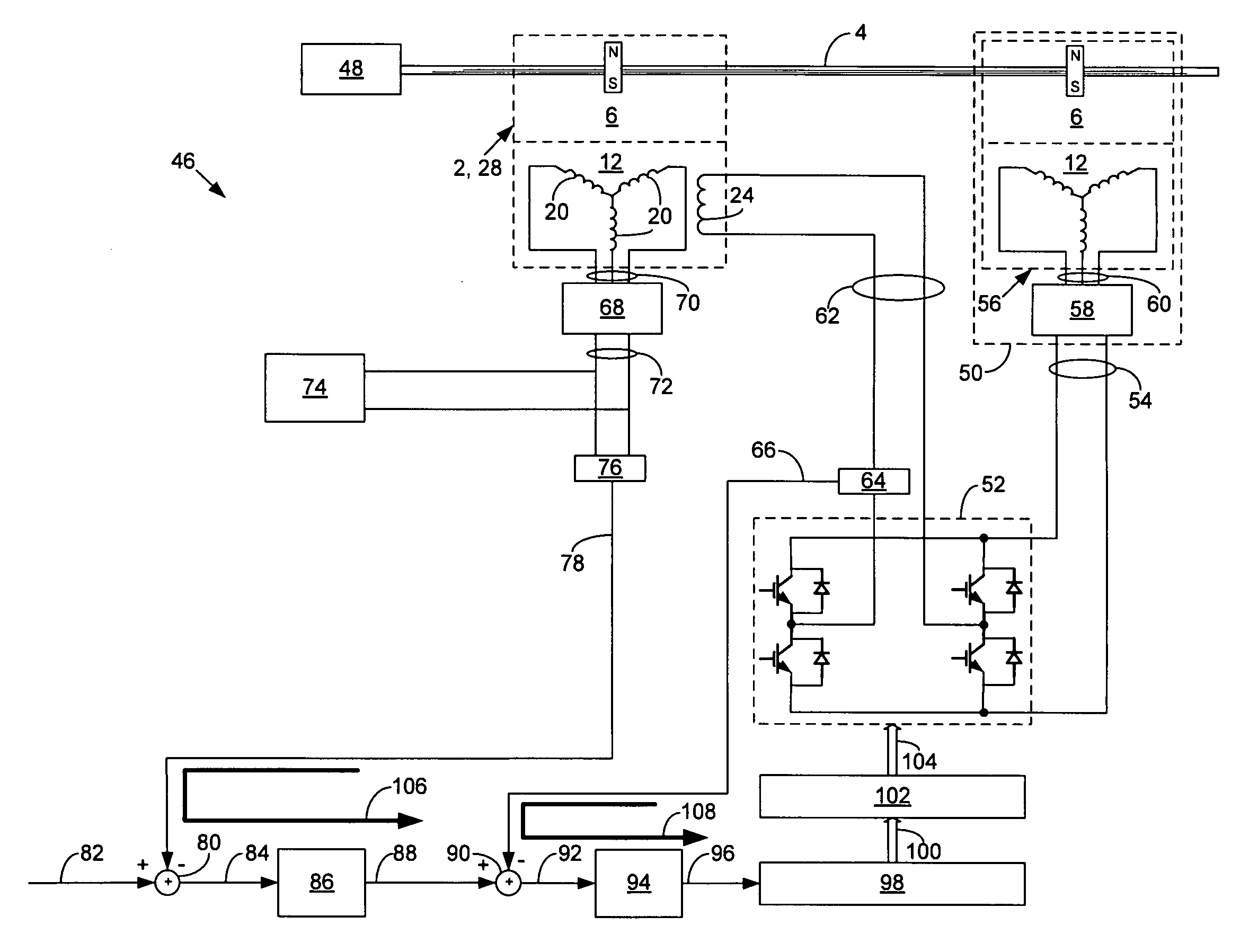
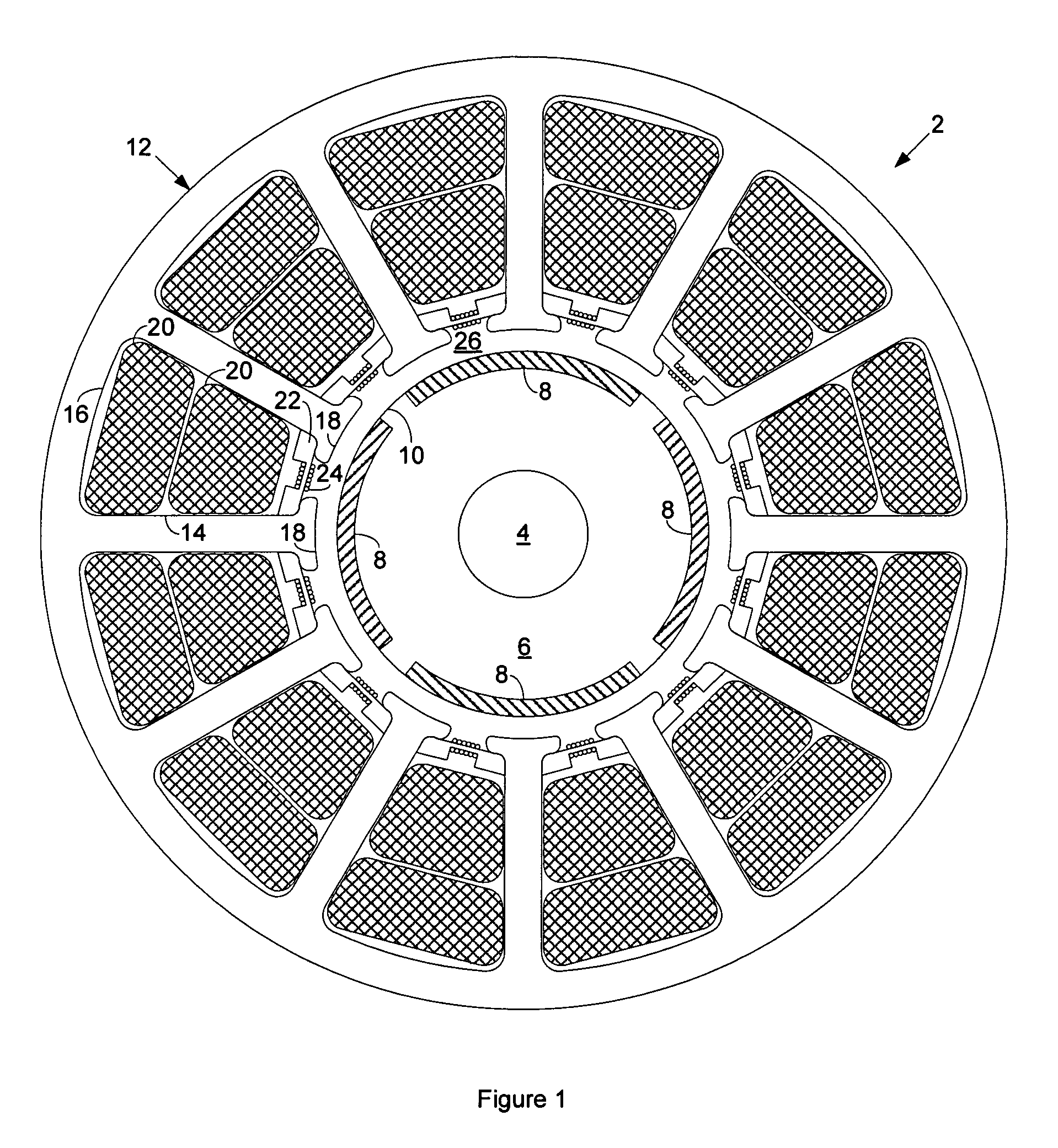
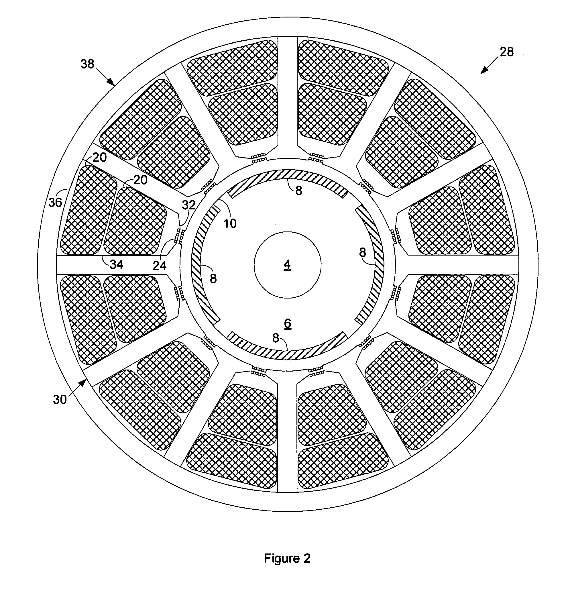
[0011]FIG. 1 is a cut-away end view of a permanent magnet (PM) dynamoelectric machine 2 according to one possible embodiment of the invention. The machine 2 has a drive shaft 4 that couples to a PM rotor assembly 6. The PM rotor assembly 6 comprises multiple PMs 8 mounted about its outer annular periphery 10. By way of example only, FIG. 1 shows the PM rotor assembly 6 with four PMs 8.

[0012]A multiple pole stator assembly 12, typically of the multiphase alternating current (AC) type, circumscribes the rotor assembly 6. The stator assembly 12 has multiple ferromagnetic stator teeth 14 coupled to a ferromagnetic stator yoke 16, one stator tooth 14 for each of the poles of the stator assembly 12. A distal end 18 of each stator tooth 14 is proximate the outer annular periphery 10 of the rotor assembly 6. The stator assembly 12 also has multiple stator coils 20 mounted between the stator teeth 14. By way of example only, FIG. 1 shows the stator coils 20 arranged in a multiphase AC two-la...


PUM


Abstract

A permanent magnet (PM) electric generator with directly controllable field excitation control comprises: a drive shaft; a PM rotor assembly with multiple PMs arranged around an outer axial periphery of the rotor assembly; a stator assembly comprising a ferromagnetic stator yoke, multiple ferromagnetic stator teeth mounted to the stator yoke with distal ends proximate the outer axial periphery of the rotor assembly separated by an air gap and multiple stator coils mounted between the stator teeth; multiple saturable ferromagnetic shunts, each shunt coupling adjacent distal ends of the stator teeth to shunt air gap magnetic flux Φg generated by the PMs across the air gap through the distal ends of the stator teeth; and multiple saturation control coils, each saturation control coil wrapped about a saturable region of an associated one of the shunts; wherein application of a control current Ic to the control coils at least partially magnetically saturates the shunts to reduce shunting of air gap magnetic flux Φg, thereby increasing magnetic flux linkage ΨM between the PMs and the stator coils and increasing generated electromagnetic force (EMF) at lower levels of rotor assembly angular velocity.

Description

FIELD OF THE INVENTION[0001]The invention relates to permanent magnet (PM) electric generators, and more particularly to PM electric generators with variable magnetic flux excitation.BACKGROUND OF THE INVENTION[0002]Electrical power generation systems powered by variable speed prime movers that require highly regulated electrical output, such as electrical power generation systems used for aeronautical applications, generally use a wound field synchronous machine (WFSM) that serves as an electrical generator. This is because it is easy to adjust rotor current to regulate electrical output of a WFSM. In aeronautical applications, the prime mover is often a gas turbine engine that has a normal angular velocity that exceeds 20,000 revolutions per minute. Due to the angular velocity limitations of the WFSM, such electrical power generation systems generally require a reduction gearbox between the prime mover and the WFSM. This increases weight, cost and complexity of the electrical powe...

Claims


Application Information

Patent Timeline
Patent Type & Authority Applications(United States)
IPC IPC(8): H02P9/14H02K21/00
CPCH02K3/20H02P9/34H02K21/046H02K3/493
Inventor GIERAS, JACEK F.ROZMAN, GREGORY I.
Owner HAMILTON SUNDSTRAND CORP
Why Eureka
Try Eureka