Frequency measurement device and measurement method

a frequency measurement and measurement device technology, applied in the field of frequency measurement, can solve the problems of not being suitable for a sensor array and not being desirable, and achieve the effect of improving the resolving power of frequency measuremen

Inactive Publication Date: 2009-10-08
SEIKO EPSON CORP
View PDF104 Cites 22 Cited by
  • Summary
  • Abstract
  • Description
  • Claims
  • Application Information

AI Technical Summary

Benefits of technology

[0008]In accordance with an advantage of some aspects of the invention, it is possible to provide a measuring method and a meas...

Problems solved by technology

As errors that could occur at the time of measurement, plus/minus 1 count errors and errors caused by jitter at trigger level could occur, and in addition, errors that originate from the oscillation stability of the quartz oscillators would be superposed on the foregoing errors.
The use of reciprocal system counters may supplement for the deficiencies described above, but would not be suitable for a senso...

Method used


Image

  • Frequency measurement device and measurement method
  • Frequency measurement device and measurement method
  • Frequency measurement device and measurement method

Examples


Embodiment Construction

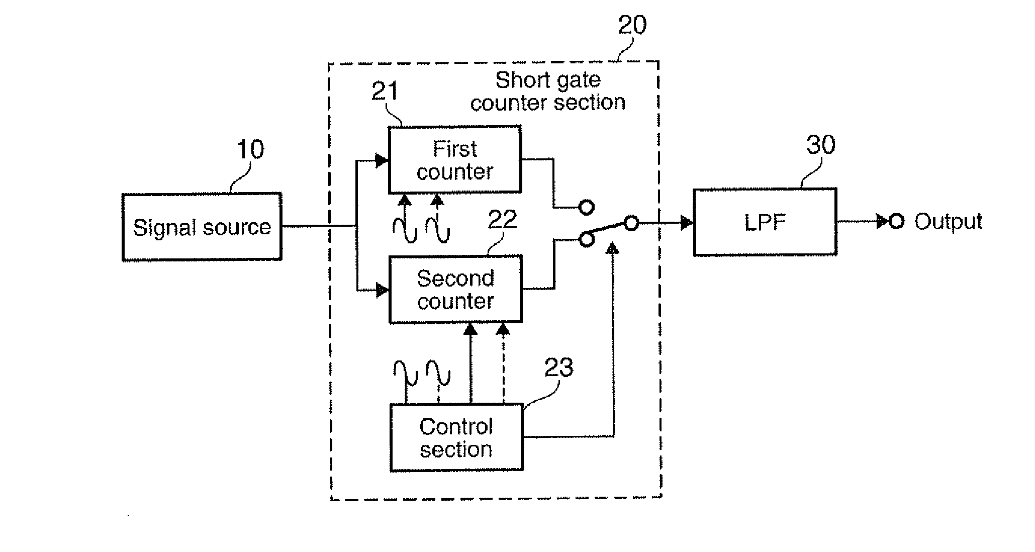
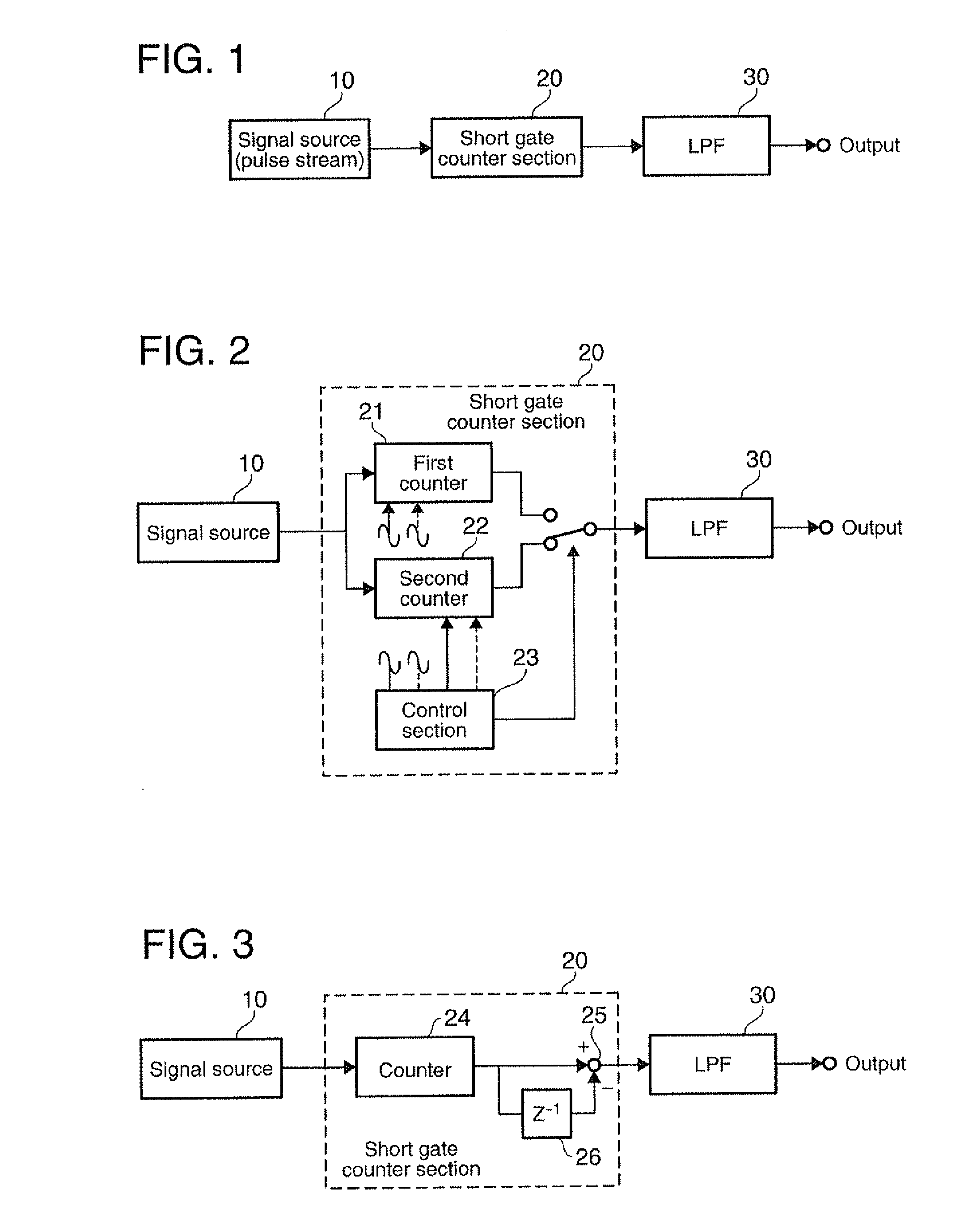
[0043]Preferred embodiments of the invention are described below with reference to the accompanying drawings. FIGS. 1-3 are schematic diagrams of frequency measurement devices in accordance with embodiments of the invention. Corresponding sections in the figures are appended with the same reference numbers.

[0044]In FIG. 1, a signal source 10 generates a pulse stream signal. The signal source 10 may be, for example, a quartz oscillator with an oscillation frequency f0 at 30 MHz, and corresponds to a detector section of an odor sensor, a gas sensor, a biosensor and the like. When odor substance adheres to the quartz oscillator, its oscillation frequency lowers according to the amount of adhered substance. The pulse stream signal is supplied to a short gate time counter section (hereafter also simply referred to as a “short gate counter”) 20. The short gate counter 20 continuously counts pulses of the supplied pulse stream signal at short gate time intervals. The count values are in a ...


PUM


Abstract

A frequency measurement device includes: a short gate time counter section that continuously measures a pulse stream signal supplied, and outputs a series of count values that behave like a pulse stream corresponding to a frequency of the pulse stream signal; and a low-pass filter that removes high frequency components from the series of count values to obtain a level signal corresponding to the frequency of the pulse stream signal supplied.

Description

[0001]Japanese Patent Application No. 2008-099721 filed on Apr. 7, 2008, is hereby incorporated by reference in its entirety.BACKGROUND[0002]1. Technical Field[0003]The invention relates to measurement of frequency, and more particularly to measurement methods and devices capable of detecting small changes in frequency.[0004]2. Related Art[0005]As frequency measurement systems, a direct count system and a reciprocal system are known. According to the direct count system, pulses passing within a predetermined gate time are counted (see, for example, Patent Document: Japanese laid-open patent application JP-A-6-501554). According to the reciprocal system, a pulse period is accurately measured, and a frequency is obtained from its time reciprocal (see, for example, Non-patent document: Kazuya Katano “How to Use Time-measuring Instruments, and Introduction to Correct Use of Measurement Instruments,” Transistor Technology, Series No. 14, February 1994, p. 331). The direct count system ma...

Claims


Application Information

Patent Timeline
IPC IPC(8): G01R23/02
CPCG01R23/10
Inventor TODOROKIHARA, MASAYOSHIKONDO, TAKAYUKI
Owner SEIKO EPSON CORP
Why Eureka
Try Eureka