Cooled Turbine Rotor Blade

a technology of rotor blades and cooling turbines, which is applied in the manufacture of engines, mechanical equipment, machines/engines, etc., can solve the problems of dead water regions now again occurring, and achieve the effects of reducing pressure losses in coolant, reducing pressure losses, and cooling the terminating wall particularly efficiently

Inactive Publication Date: 2009-10-08
SIEMENS AG
View PDF4 Cites 6 Cited by
  • Summary
  • Abstract
  • Description
  • Claims
  • Application Information

AI Technical Summary

Benefits of technology

[0011]In one particularly advantageous refinement, the terminating wall, which is likewise frequently subject to local overheating and is also referred to as a crown base, can also be impingement-cooled on the basis of the coolant jet passing through the opening, in such a way that this likewise makes it possible to cool the terminating wall particularly efficiently. To do this, the opening just has to be inclined such that its longitudinal extent is directed at the terminating wall.
[0012]The rib which is adjacent to the trailing edge is preferably curved in the area of the airfoil tip. In this case, the rib—seen from the attachment area to the tip area—is curved toward the leading edge thus making it possible to provide an essentially constant flow cross-sectional area in a part of the direction-changing area between two adjacent coolant channels. This reduces the pressure losses in the coolant. In order to provide a particularly lightweight turbine rotor blade, the rib has an essentially constant rib thickness along its curvature.
[0013]In one advantageous development of the invention, the inner face of the terminating wall is equipped with turbulators, thus making it possible to improve the cooling of the terminating wall or of the crown base in a simple manner. Depending on the configuration of the turbine rotor blades, it is possible for a coolant to flow sequentially or else in parallel through the adjacent cooling channels. If the flow passes in parallel through the coolant channels, care must be taken to ensure that there is an adequate pressure gradient between them, in order to obtain a coolant flow which passes through the opening.

Problems solved by technology

However, the curvature of the rib results in an acute-angled corner area in the adjacent cooling channel, in which dead-water regions could now once again occur.

Method used


Image

  • Cooled Turbine Rotor Blade
  • Cooled Turbine Rotor Blade

Examples


Embodiment Construction

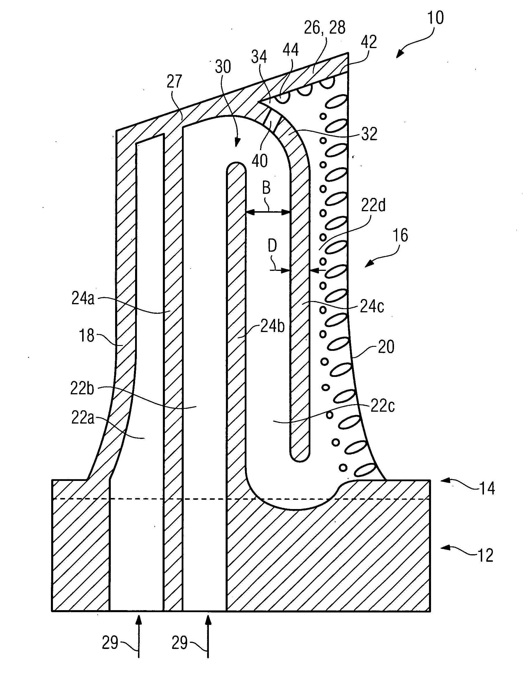
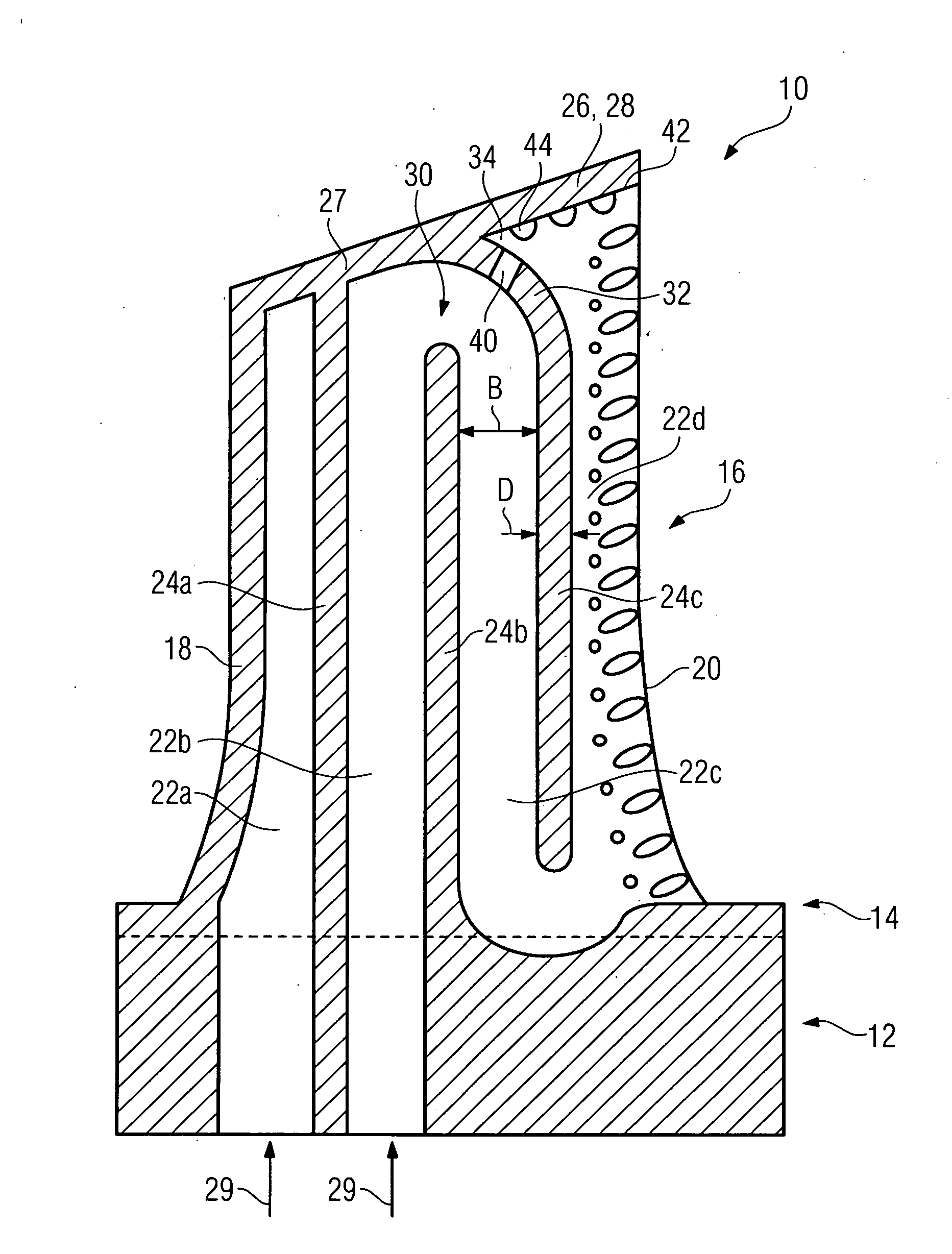
[0015]The FIGURE shows a longitudinal section through a turbine rotor blade 10 which is produced by a casting method. The turbine rotor blade 10, which is therefore integral, has an attachment area 12, with a firtree-shaped cross section, with a platform 14 and an airfoil profile 16 arranged thereon. The airfoil profile 16, which has an aerodynamically profiled cross section, is formed by a suction-side blade wall and a pressure-side blade wall, which each extend from a leading edge 18 to a trailing edge 20 and in this case surround a cavity, which is arranged in the interior of the airfoil profile 16 and in which a plurality of cooling channels 22a, 22b, 22c, 22d are provided. The cooling channels 22 are adjacent to one another and each run approximately parallel to the leading edge 18. The mutually adjacent cooling channels 22 are each separated from one another in places by a rib 24a, 24b, 24c which connects the pressure-side blade wall to the suction-side blade wall. The cooling...


PUM


Abstract

A cooled turbine rotor blade for a gas turbine which is traversed axially by flow and is equipped with an attachment area and an airfoil profile is provided. Meandering cooling channels with interposed deflecting regions are provided in the interior of the airfoil profile. In the deflecting regions, it is possible to prevent dead water regions, which are generated in the prior art, by virtue of at least one of the ribs running so as to curve towards the leading edge or towards the trailing edge in the region of the airfoil tip. At the same time, an opening is provided in the curvature of the rib. Through this opening a part of the coolant flows in the deflecting region and can pass over into the adjacent cooling duct.

Description

[0001]This application is the US National Stage of International Application No. PCT / EP2007 / 056425, filed Jun. 27, 2007 and claims the benefit thereof. The International Application claims the benefits of European application No. 06018490.0 EP filed Sep. 4, 2006, both of the applications are incorporated by reference herein in their entirety.FIELD OF INVENTION[0002]The invention relates to a cooled turbine rotor blade.BACKGROUND OF INVENTION[0003]By way of example, a turbine rotor blade of this generic type and having an airfoil profile is known from EP 0 735 240 A1. A plurality of mutually adjacent cooling channels are provided in order to cool the airfoil profile, are arranged in a meandering shape, and a coolant can flow through them sequentially. The cooling channels in this case each run parallel to the leading edge. Respectively adjacent cooling channels are separated from one another by ribs, with the ribs ending in a direction-reversal area in which the adjacent cooling chan...

Claims


Application Information

Patent Timeline
Patent Type & Authority Applications(United States)
IPC IPC(8): F01D5/18F01D25/12
CPCF01D5/187F05D2240/122F05D2240/304F05D2260/2212Y02T50/673Y02T50/676F05D2260/202F05D2250/185Y02T50/60
Inventor GROSS, HEINZ-JURGEN
Owner SIEMENS AG
Why Eureka
Try Eureka