Method for metal-resin joining and a metal-resin composite, a method for glass-resin joining and a glass-resin composite, and a method for ceramic-resin joining and a ceramic-resin composite

a metal-resin and composite technology, applied in the field of metal-resin joining and metal-resin composites, can solve the problems of limited application, reduced production tact, and inability to achieve precise and precise joining, and achieve the effect of small joint and precise and fine jointing

Inactive Publication Date: 2009-10-08
OSAKA UNIV
View PDF3 Cites 19 Cited by
  • Summary
  • Abstract
  • Description
  • Claims
  • Application Information

AI Technical Summary

Benefits of technology

[0040]The method for joining of the present invention enables strong joining between a metallic material, a glass material or a ceramic material and a resin material. Specifically, by heating the interior portion of the resin material using a laser light source, an ionizing radiation source or the like as a heating source, fine bubbles are generated in the resin and the resin has a structure enclosing bubbles, whereby the pressure and suction force resulting from generation of bubbles can be increased, and strong joining between the metallic material, the glass material or the ceramic material and the resin material can be accelerated.
[0041]Furthermore, many advantages are provided by using a laser light source, an ionizing radiation source or the like as a heating source. Firstly, since the laser light source and the ionizing radiation source allow topical heating, they can make a small joint. Therefore, a joint having a size of a rivet and the rivet itself used in rivet fastening become unnecessary, which can prevent a joint from becoming large and heavy. Secondly, in the method for joining using an adhesive, precise pinpoint joining is difficult because the adhesive is wet and extended, whereas a laser light source, for example, can decrease the beam diameter to the order of micron, a precise and fine joint can therefore be obtained. Thirdly, since the adsorption force generated during cooling and solidification of the resin material acts more advantageously as the surface becomes plane, limitation of the joining surface can also be alleviated. Fourthly, the time of irradiation of laser light required for joining is shorter than the time required for curing an adhesive, and the time does not act as a step for rate-limiting the production. Furthermore, when the joining is effected using laser light, occurrence of oxidation and deterioration can sometimes be suppressed more than the case of joining by an adhesive, which makes maintenance and control relatively easy. Fifthly, by selecting the wavelength of laser light that permeates a resin material or the ionizing radiation source, heating can be effected either from the side of a metallic material, a glass material or a ceramic material, or from the side of a resin material, which eliminates limitation on the direction of application of heat by a heating source. This is very advantageous in view of manufacturing technique since freedom of designing and freedom of selection of materials are increased. In fact, in the joining of resin materials using laser light, limitation that laser light can be irradiated only from one side sometimes exists.

Problems solved by technology

For joining using laser, a method for joining metallic materials or resin materials by welding and deposition is practically used, but joining between a metallic material and a resin material has not been effected yet.
However, the field of application is limited under the current situation in the method using rivet fastening or an adhesive, which is a conventional method for joining a metallic material and a resin material.
On the other hand, in adhesion, the size and weight are not increased, but there are technical problems that precise pinpoint joining is difficult because the adhesive is wet and extended, that the surface to be adhered is restricted, for example, adhesive strength on an uneven surface is higher than that on a plane surface, and that production tact is decreased due to long cure time and maintenance and control of the state of the adhesive are difficult during production.
In the joining using laser, selection of materials is limited since a resin material being transparent relative to the laser wavelength and a resin material being opaque relative to the laser wavelength must be used as in the joining of resins, and there is a problem in manufactural technology that laser irradiation can be effected only from the transparent resin material side.
The same problems also exist in joining of a glass material and a resin material and joining of a ceramic material and a resin material.

Method used


Image

  • Method for metal-resin joining and a metal-resin composite, a method for glass-resin joining and a glass-resin composite, and a method for ceramic-resin joining and a ceramic-resin composite
  • Method for metal-resin joining and a metal-resin composite, a method for glass-resin joining and a glass-resin composite, and a method for ceramic-resin joining and a ceramic-resin composite
  • Method for metal-resin joining and a metal-resin composite, a method for glass-resin joining and a glass-resin composite, and a method for ceramic-resin joining and a ceramic-resin composite

Examples


example 1

[0100]Hereinafter, Examples of the present invention are described with reference to the drawings.

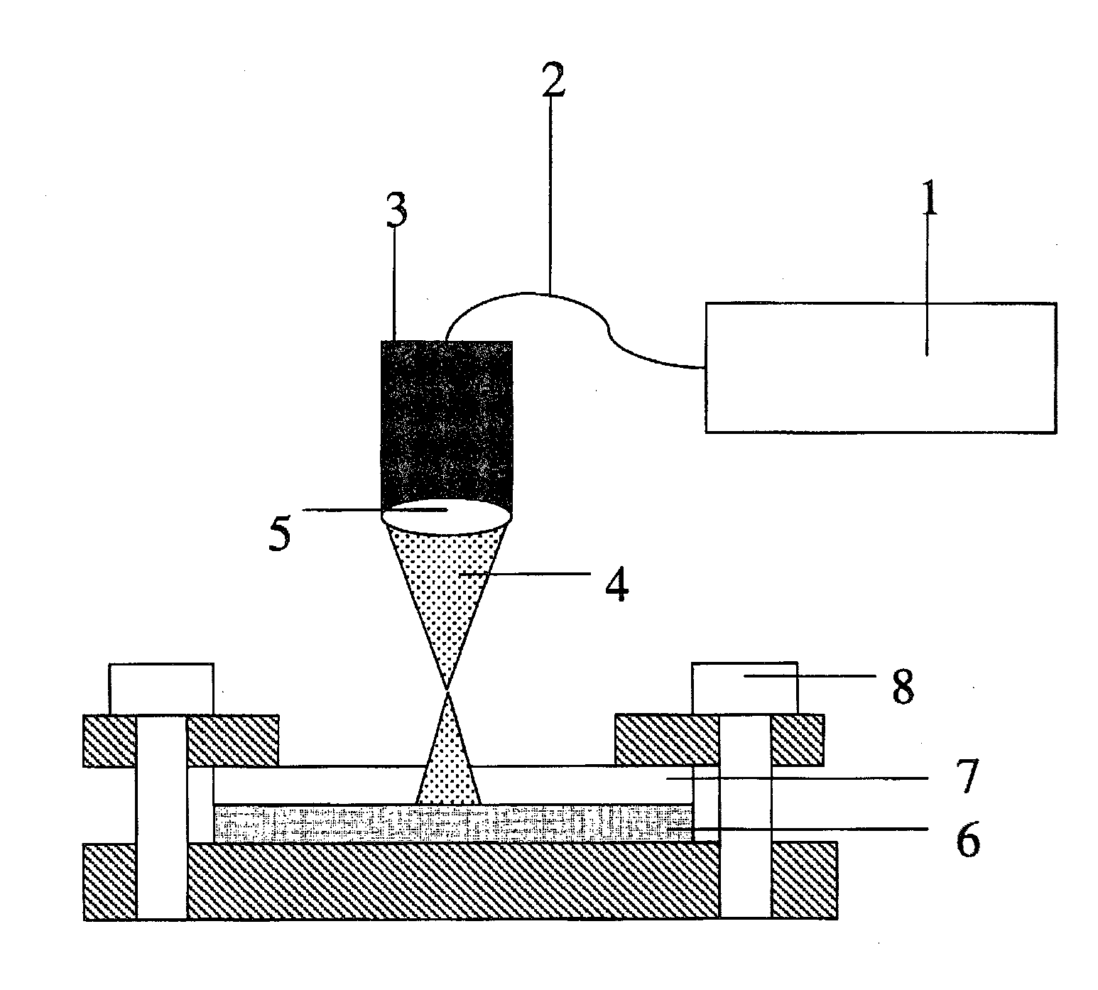
[0101]FIG. 1 is a view that shows the constitution of the method for a metal-resin joining of Example 1. As shown in FIG. 1, fiber laser light 4 having a wavelength of 1090 nm was introduced to a laser processing head 3 from a fiber laser oscillator 1 via a fiber 2 and focused by a light focus lens 5 having a focal point distance of 80 mm. At the position 15 mm away from the position in the focal point in the direction away from the lens, a metallic material which is a workpiece 6 (pure titanium), and a resin material which is a workpiece 7 (polycarbonate, “Novaflex 7025IR” manufactured by Mitsubishi Engineering-Plastics Corporation, glass transition temperature=150° C. (Tmg compliant with the DSC method JIS K 7121), loading deflection temperature under loading of catalogue value=129° C. (loading: 1.80 MPa) / 142° C. (loading: 0.45 MPa), compliant with ISO 75-1, 75-2) were superposed each...

example 2

[0102]FIG. 6 is a view that shows the constitution of the method for a metal-resin joining of Example 2. As shown in FIG. 6, YAG laser light 17 having a wavelength of 1064 nm was introduced to a laser processing head 16 from a YAG laser oscillator 15 via a fiber 2 and focused by a light focus lens 18 having a focal point distance of 200 mm. At the position 30 mm away from the position in the focal point in the direction away from the lens, a metallic material which is a workpiece 19 (stainless steel SUS 304), and a resin material which is a workpiece 20 (PA12 amorphous polyamide, “T-714H” manufactured by Toyobo Co., Ltd., glass transition temperature=160° C. (Tmg compliant with the DSC method JIS K 7121), loading deflection temperature under loading=130° C. (loading: 1.80 MPa) / 145° C. (loading: 0.45 MPa), compliant with ISO 75-1, 75-2) were superposed each other and fixed by a clamp 8, and traveled at the traveling speed of 30 mm / s during irradiation of the laser light having the po...

example 3

[0103]The portion to be joined of the metallic material and the resin material was heated in a method similar to that of Example 1 under the following conditions. The surface appearance and state of the bubbles at the joint were observed while changing laser power, and the tensile shear loading and the tensile shear strength of the joint were also measured.

[0104]Metallic material: stainless steel SUS 304 plate (thickness: 2 mm)

[0105]Resin material: PA12 amorphous polyamide plate (“T-714H” manufactured by Toyobo Co., Ltd.) (thickness: 2 mm)

[0106]Material at heating source side: resin material

[0107]Heating source: YAG laser[0108]Power (changed between 0 to 1000 W)[0109]Defocusing distance: 20 mm (beam diameter: 5 mm)[0110]Traveling speed: 10 mm / s

[0111]The surface appearance (power: 110 W, 300 W, 560 W and 850 W) of the joint when the laser power was changed is shown in FIG. 11. As is apparent from FIG. 11, the bubbles of the resin material began to generate at the laser power of 110 W...


PUM

PropertyMeasurementUnit
tensile shear strengthaaaaaaaaaa
diameteraaaaaaaaaa
diameteraaaaaaaaaa

Abstract

The present invention provides a method for joining a metallic material, a glass material or a ceramic material, and a resin material, that have no limitation in their field of application and that can form a strong joint by an easy method. The method for joining a metallic material, a glass material or a ceramic material, and a resin material is characterized in that joining is effected by heating a portion to be joined, in such a state that the metallic material, glass material or ceramic material is coupled with the resin material, to a temperature at which bubbles (preferably the sphere equivalent diameter from 0.01 mm to 5.0 mm) are generated in the resin material at the portion to be joined. As a heating source for heating the portion to be joined, a laser light source is used, especially.

Description

TECHNICAL FIELD OF THE INVENTION[0001]The present invention relates to a method for joining a metallic material and a resin material, and a metal-resin composite having a joint joined by the method, and particularly relates to a method for joining a metallic material and a resin material which can form a strong joint by heating the portion to be joined between the metallic material and the resin material to a specific temperature. Furthermore, the present invention also relates to a method for glass-resin joining and a glass-resin composite, and to a method for ceramic-resin joining and a ceramic-resin composite.BACKGROUND ART[0002]As conventional methods for joining a metallic material and a resin material, a method using rivet fastening and a method using adhesives are exemplified. Rivet fastening is a physical fastening method comprising knocking a rivet having a diameter of several millimeters to several tens of millimeters into a metallic material and a resin material in a stat...

Claims


Application Information

Patent Timeline
Patent Type & Authority Applications(United States)
IPC IPC(8): B29C65/16B32B15/08
CPCB23K26/3206B29C66/91641B23K26/3273B23K26/328B29C65/16B29C65/1616B29C65/1674B29C65/44B29C65/665B29C65/8207B29C66/30326B29C66/45B29C66/742B29C66/7461B29C66/7465B29C66/82661B29C66/919B29C66/91921B29C2035/0838B29K2077/00B29K2101/12B29K2305/00B29K2309/02B29K2309/08B29K2995/0039B32B15/08B23K26/3266B29C66/91411B29C65/1635B29C66/91221B29C65/8215B29C65/8253B29C66/30325B29C65/00B23K26/32B29C66/71B29C66/7212B29C66/73117B29C66/73771B29C66/7392B23K2103/16B23K2103/172B23K2103/50B23K2103/52Y10T428/31678B29K2307/04B29K2069/00B29K2067/006B29K2067/003B29K2067/00B29C65/02
Inventor KATAYAMA, SEIJIKAWAHITO, YOSUKEKUBOTA, SHUJITANGE, AKIO
Owner OSAKA UNIV
Why Eureka
Try Eureka