
Self-actuated cylinder and oscillation spirometer

a self-actuated, cylinder technology, applied in the direction of dynamo-electric machines, sensors, diagnostics, etc., can solve the problems of multiplicity of components, inability to easily minimize their size, and increase the overall system cost of the system

Active Publication Date: 2009-10-08
THORASYS THORACIC MEDICAL SYST INC
View PDF4 Cites 12 Cited by
  • Summary
  • Abstract
  • Description
  • Claims
  • Application Information

AI Technical Summary

Benefits of technology

[0010]An object of the present invention is to propose a self-actuated cylinder that satisfies at least one above-mentioned need.

Problems solved by technology

While in some cases, the actuator and the position measurement are somewhat integrated, e.g. when a stepper motor is used, there is no known solution in the public domain that combines the actuator and the cylinder into a single device in such a way that there is no need for connecting rods or gears whatsoever.
First, their size cannot easily be minimized because space must be provided for the connecting rods.
For example, a setup based on a DC linear actuator can easily require an overall length that is greater than four times its actual stroke length, Furthermore, the connecting gears and rods can pose problems and / or reduce performance due to weight, insufficient stiffness, poor alignment, play in joints, friction and dynamic properties, Finally, the multiplicity of components adds to the overall system cost.
However, current FOT devices are limited because of their large size, poor low frequency performance and poor coupling between the patient and the device.

Method used


Image

  • Self-actuated cylinder and oscillation spirometer
  • Self-actuated cylinder and oscillation spirometer
  • Self-actuated cylinder and oscillation spirometer

Examples


Embodiment Construction

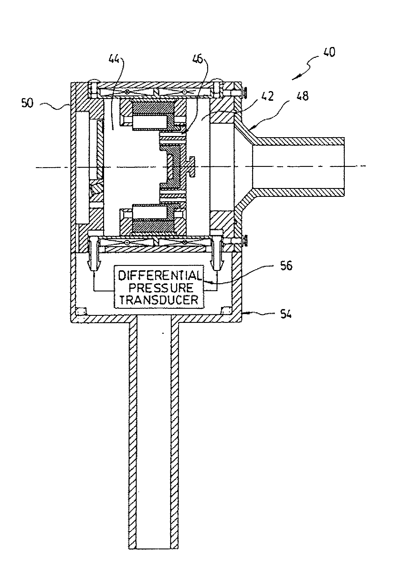
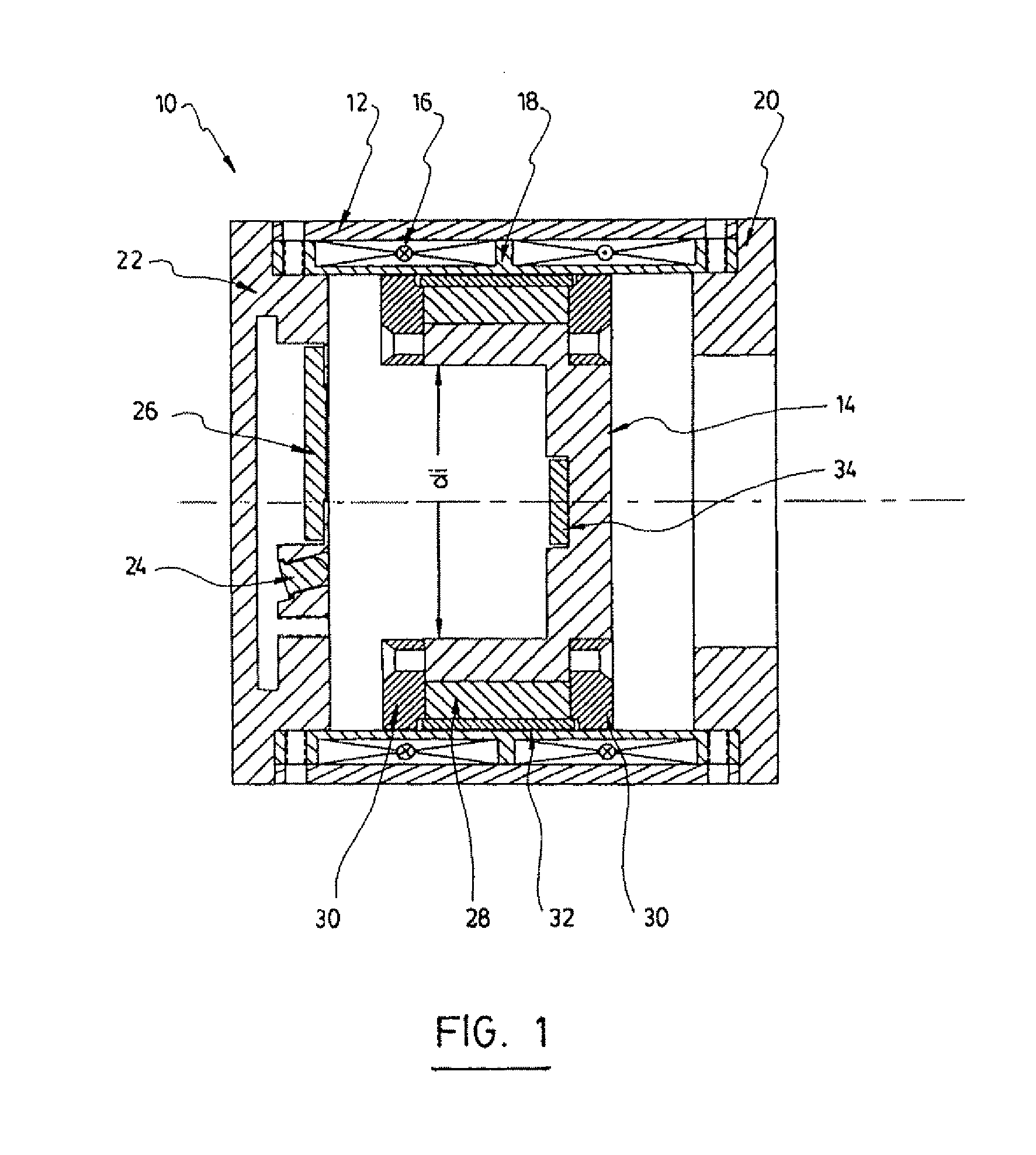
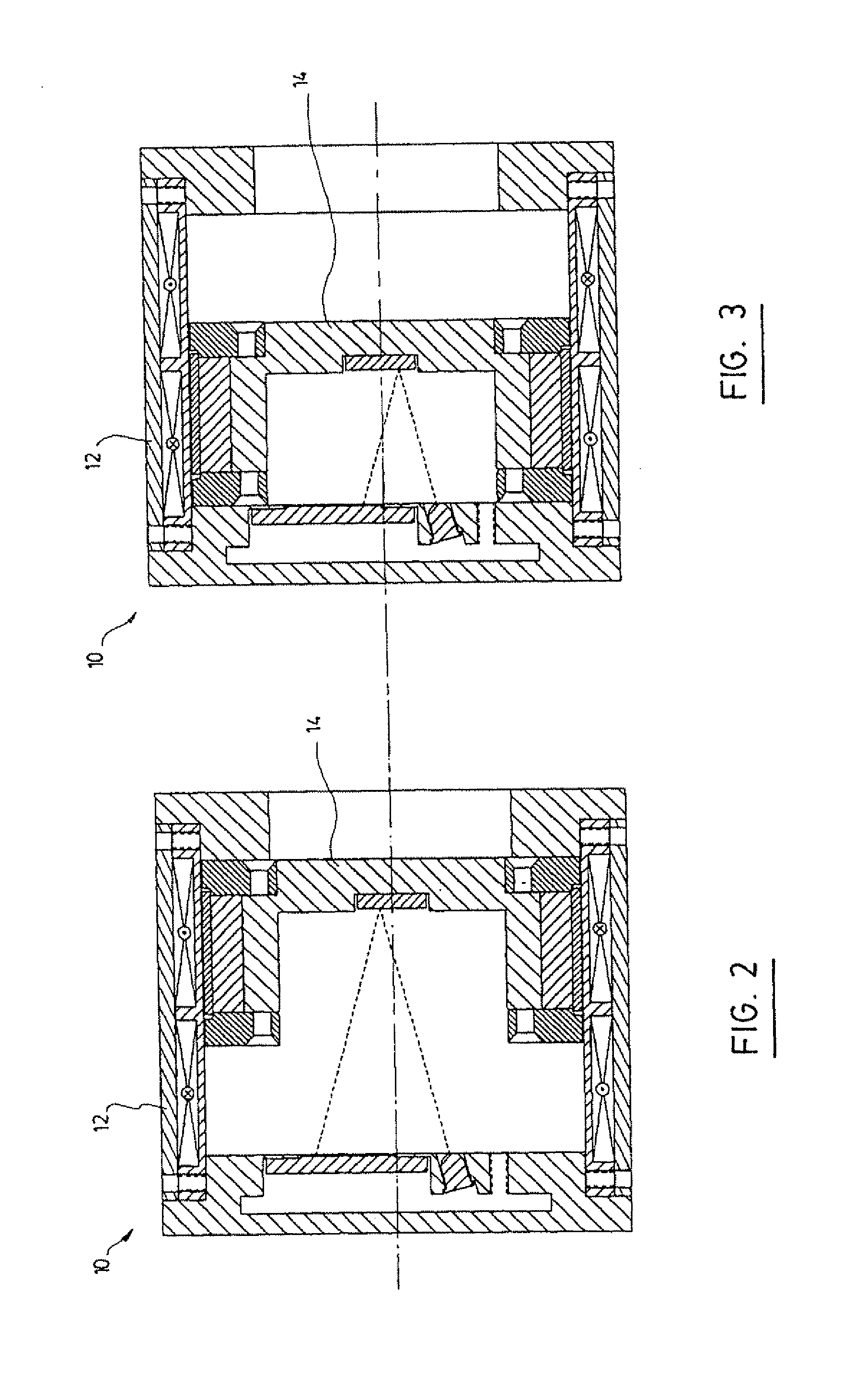
[0029]Referring to FIGS. 1 to 3, the present invention provides a self-actuated cylinder 10 comprising a cylinder housing 12 comprising electromagnetic force generating means to generate electro-magnetic forces and a piston 14 within the cylinder housing 12, wherein the electro-magnetic forces act directly on the piston 14 to displace the piston 14 within said cylinder housing 12.

[0030]The basic concept of the Self-Actuated Cylinder (SAC) is that the force generated by the electromagnetic actuator acts directly on the piston. In other words, one component or assembly acts both as the moving part of the actuator and as the piston. A second component or assembly acts both as the stationary part of the actuator and as the cylinder. Preferably, the transmission of force is based on the principles of a moving magnet linear electro-magnetic actuator. In an alternate embodiment of the present invention, a moving coil design may be used.

[0031]In accordance with a preferred embodiment of the...


PUM


Abstract

A self-actuated cylinder comprising a cylinder housing comprising electro-magnetic force generating means to generate electro-magnetic forces, and a piston within the cylinder housing, wherein the electro-magnetic forces act directly on the piston to displace the piston within the cylinder housing. The self-actuated cylinder can be used as an oscillation spirometer to determine air flow, an input impedance or Forced Oscillation pulmonary mechanics.

Description

FIELD OF THE INVENTION[0001]The present invention relates to a self-actuated cylinder for use in several kinds of equipment, including integrated devices for spirometry and forced oscillation pulmonary mechanics.BACKGROUND OF THE INVENTION[0002]There is a general interest in servo-controlled piston / cylinder pumps. For example, SCIREQ's flagship product, the flexiVent™, is essentially a computer-controlled piston pump that is customized for use as a mechanical ventilator and measuring device of pulmonary mechanics for pre-clinical research.[0003]Servo-controlled piston pumps typically consist of i) an actuator, ii) a piston / cylinder assembly, iii) a position / displacement measurement device, and iv) gears, rods or other means of connecting the other components together in order to transmit force from one component to the other. While in some cases, the actuator and the position measurement are somewhat integrated, e.g. when a stepper motor is used, there is no known solution in the pu...

Claims


Application Information

Patent Timeline
Patent Type & Authority Applications(United States)
IPC IPC(8): A61B5/091F04B35/04F15B21/02
CPCA61B5/085A61B5/087H02K33/16H01F2007/1692H01F2007/185H01F7/1615
Inventor SCHUESSLER, THOMASUROVITCH, ILAN BENJAMIN
Owner THORASYS THORACIC MEDICAL SYST INC
Learn More