Method of manufacturing combustor components

a technology of combustor and components, which is applied in the field of combustor components, can solve the problems of increasing the time needed to fabricate such components, reducing the efficiency of combustor manufacturing, and reducing the cost of combustor manufacturing,

Inactive Publication Date: 2009-10-15
GENERAL ELECTRIC CO
View PDF40 Cites 46 Cited by
  • Summary
  • Abstract
  • Description
  • Claims
  • Application Information

AI Technical Summary

Problems solved by technology

Because of limited fuel pressure availability and a wide range of required fuel flow, many fuel injectors include pilot and main nozzles, with only the pilot nozzles being used during start-up, and both nozzles being used during higher power operation.
Conventional combustor components, such as, for example, fuel nozzles, are generally expensive to fabricate and / or repair because the conventional fuel nozzle designs include a complex assembly and joining of more than thirty components.
More specifically, the use of braze joints can increase the time needed to fabricate such components and can also complicate the fabrication process for any of several reasons, including: the need for an adequate region to allow for braze alloy placement; the need for minimizing unwanted braze alloy flow; the need for an acceptable inspection technique to verify braze quality; and, the necessity of having several braze alloys available in order to prevent the re-melting of previous braze joints.
Moreover, numerous braze joints may result in several braze runs, which may weaken the parent material of the component.
The presence of numerous braze joints can undesirably increase the weight and manufacturing cost of the component.

Method used


Image

  • Method of manufacturing combustor components
  • Method of manufacturing combustor components
  • Method of manufacturing combustor components

Examples


Embodiment Construction

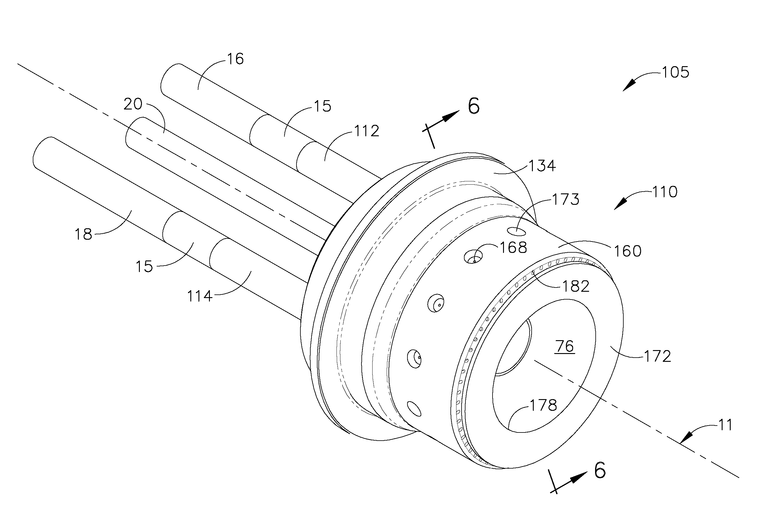
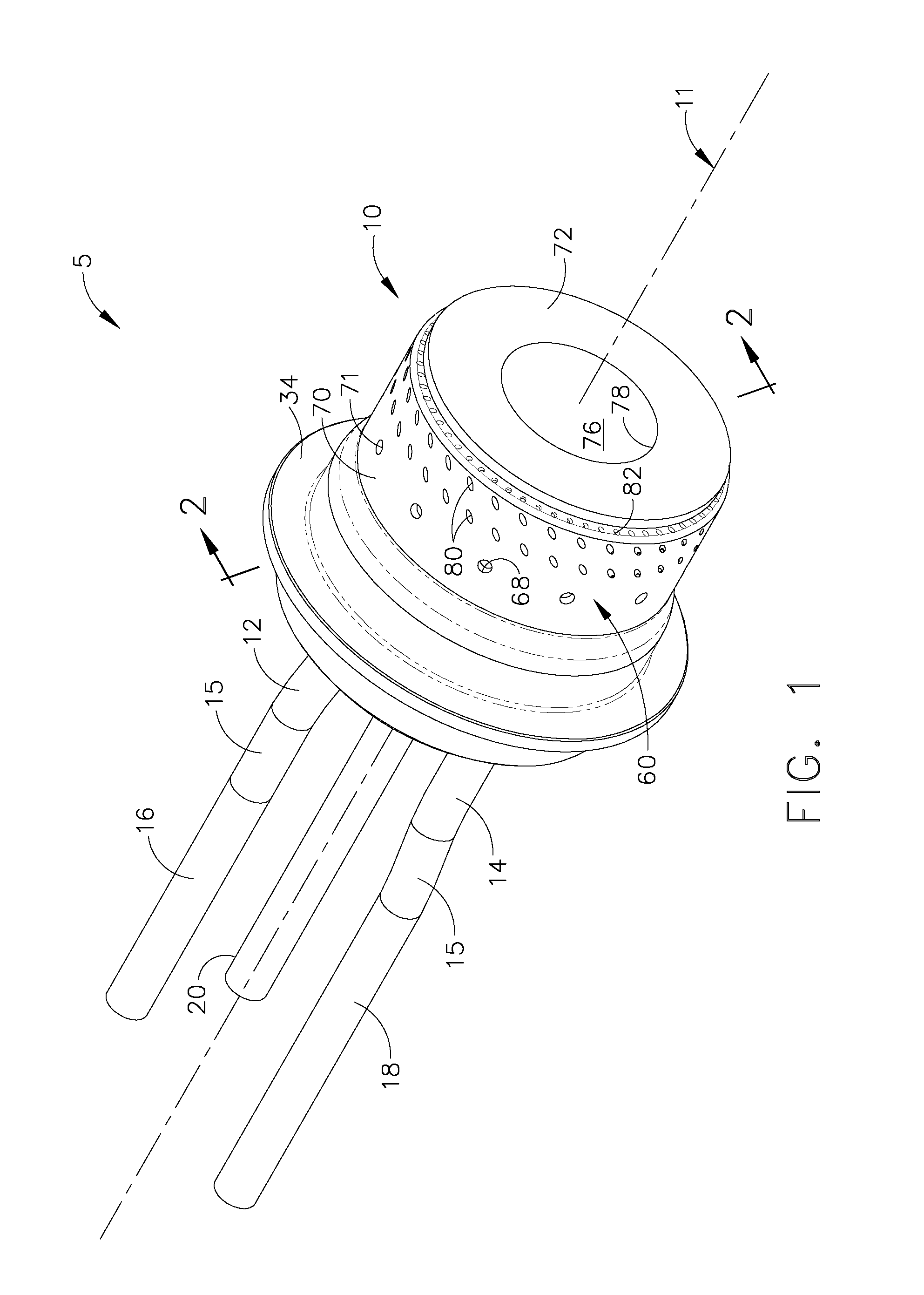
[0021]Referring to the drawings wherein identical reference numerals denote the same elements throughout the various views, FIG. 1 shows a fuel nozzle 5 according to an exemplary embodiment of the present invention. The fuel nozzle has an axis 11, a fuel nozzle tip 10 comprising a fuel supply conduit 12, 14 that receive and supply fuel into the fuel nozzle tip 10, a fuel distributor 60 that distributes the fuel, a center body 70, a mixing chamber 76 wherein fuel and air are mixed, and a heat shield 72. In the exemplary embodiment shown in FIG. 1, two fuel supply conduits 12, 14 are shown, for example, that are coupled to corresponding fuel supply lines 16, 18. A third supply line 20 supplies fuel to a pilot fuel injector 22 that is located along the axis inside the fuel nozzle tip 10.

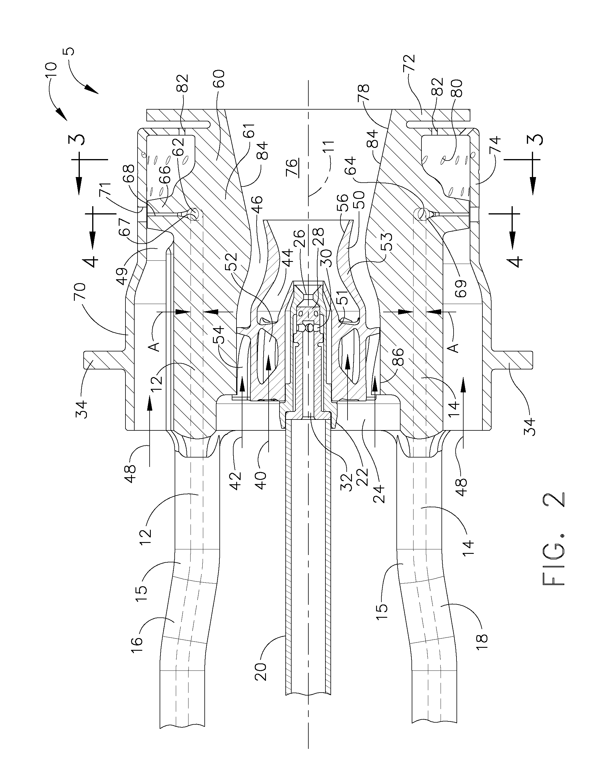
[0022]The components and features of the exemplary embodiment of the present invention shown in FIG. 1 are more clearly seen in the axial cross sectional view shown in FIG. 2. FIG. 2 shows the fuel nozz...


PUM

PropertyMeasurementUnit
particle sizeaaaaaaaaaa

Abstract

A method for fabricating a unitary component for a combustor is disclosed, said method comprising the steps of determining three-dimensional information of the unitary component, converting the three-dimensional information into a plurality of slices that each define a cross-sectional layer of the unitary component, and successively forming each layer of the unitary component by fusing a metallic powder using laser energy. A fuel nozzle component is disclosed, comprising a body having a unitary construction wherein the body is made by using a rapid manufacturing process.

Description

BACKGROUND OF THE INVENTION[0001]This invention relates generally to combustors, and more specifically to fuel nozzle components having a unitary construction and fuel nozzle assemblies using such components.[0002]Turbine engines typically include a plurality of fuel nozzles for supplying fuel to the combustor in the engine. The fuel is introduced at the front end of a burner in a highly atomized spray from a fuel nozzle. Compressed air flows in around the fuel nozzle and mixes with the fuel to form a fuel-air mixture, which is ignited by the burner. Because of limited fuel pressure availability and a wide range of required fuel flow, many fuel injectors include pilot and main nozzles, with only the pilot nozzles being used during start-up, and both nozzles being used during higher power operation. The flow to the main nozzles is reduced or stopped during start-up and lower power operation. Such injectors can be more efficient and cleaner-burning than single nozzle fuel injectors, a...

Claims


Application Information

Patent Timeline
Patent Type & Authority Applications(United States)
IPC IPC(8): F02C7/22B22F7/00
CPCB22F3/1055F23R3/286F23R3/14F23D2213/00B33Y80/00Y02P10/25B22F10/28B22F10/80
Inventor MCMASTERS, MARIE ANNLOHMUELLER, STEVEN JOSEPHBOEHM, RANDALL CHARLES
Owner GENERAL ELECTRIC CO
Why Eureka
Try Eureka