Wireline System

a wireline system and wireline technology, applied in the field of wireline systems, can solve the problems of potentially damaging the core quality of the hole, and achieve the effect of preventing rope slack and maintaining rope tension

Inactive Publication Date: 2009-10-15
TGH US
View PDF28 Cites 33 Cited by
  • Summary
  • Abstract
  • Description
  • Claims
  • Application Information

AI Technical Summary

Benefits of technology

[0010]This form of drilling, sampling or measuring is faster than conventional methods because the drill string does not have to be disassembled to recover the core barrel or measuring device from the bottom of the drill string and reassembled again when each core or data measurement is retrieved. The wireline method also does not have the hole collapse issues that can frequently occur in some soil conditions because the drill string can stay in the hole during the operations. Hole collapse is potentially damaging to core quality and is common in conventional drilling operations.
[0016]In accordance with an added feature of the invention, grabber and alignment arms deliver a drilling tool from a removable tool rack to a position along the common centerline for the drillstring. A foot clamp cooperates with the grabber and alignment arms for exchanging a drilling tool. A tensioner maintains tension in the rope and prevents rope slack when the rope is deployed out.

Problems solved by technology

Hole collapse is potentially damaging to core quality and is common in conventional drilling operations.

Method used


Image

  • Wireline System
  • Wireline System
  • Wireline System

Examples


Embodiment Construction

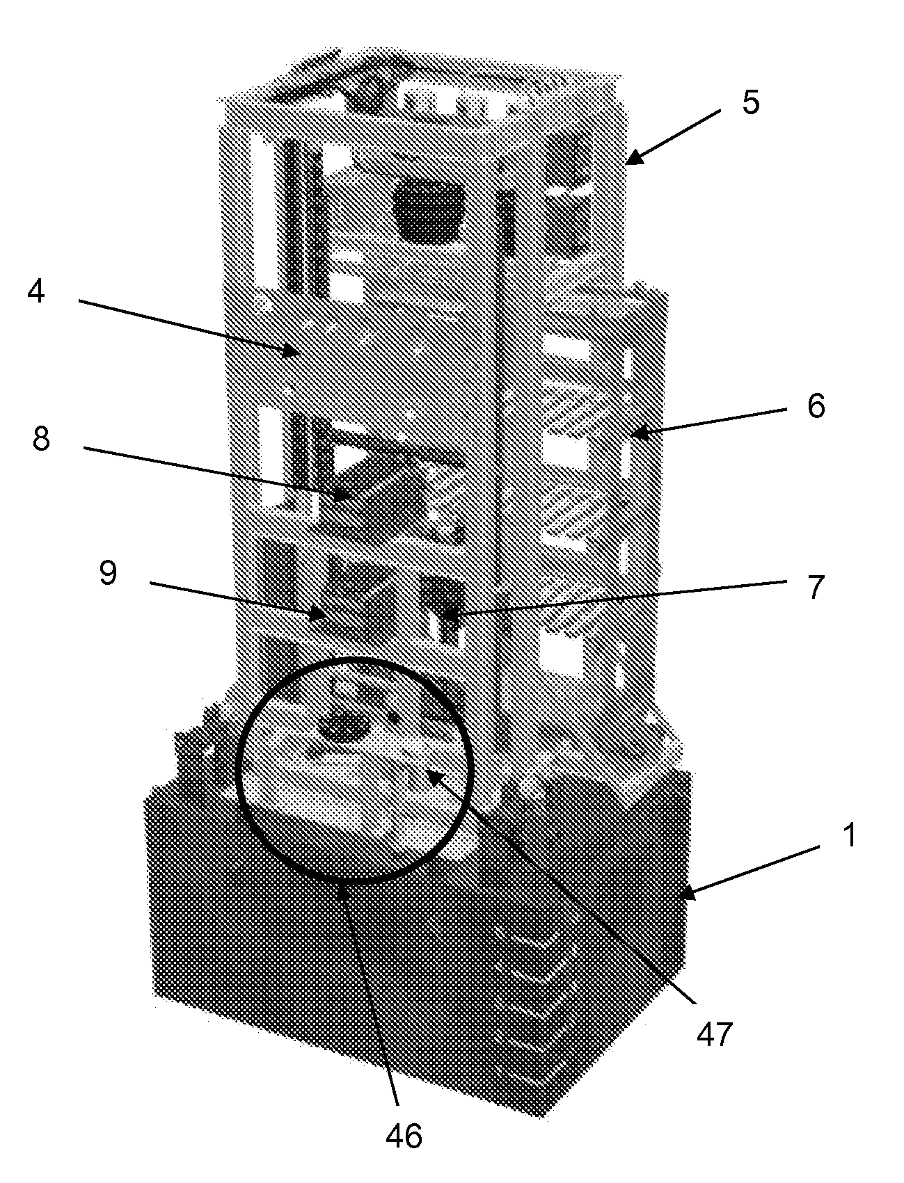
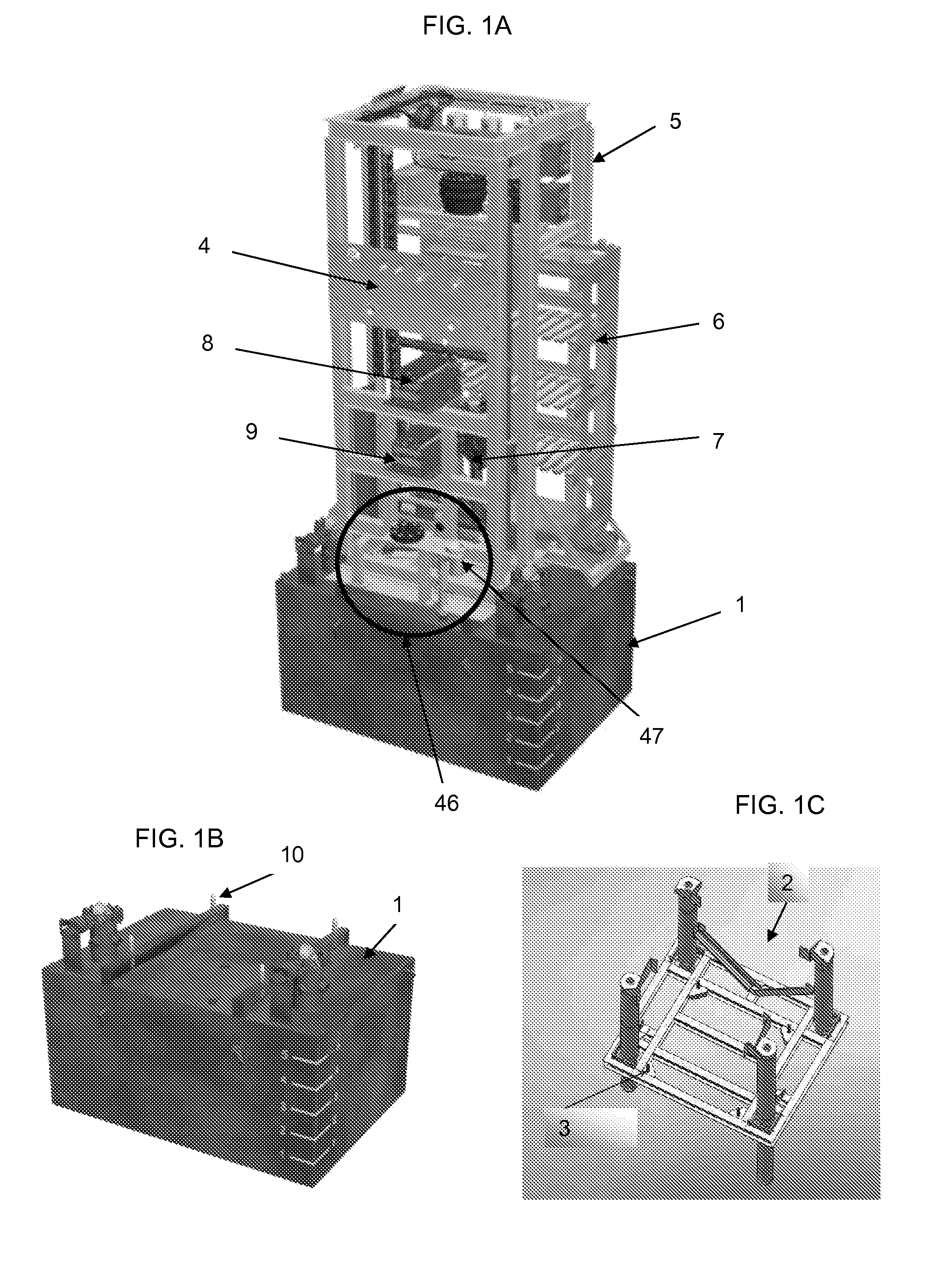
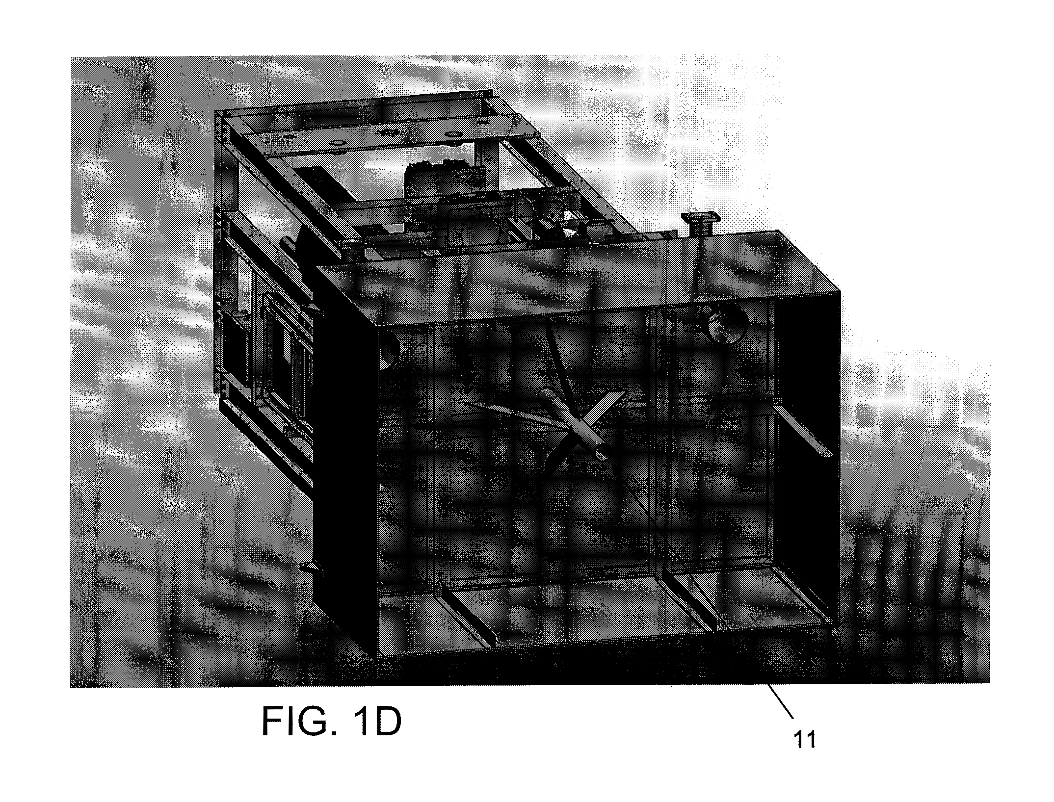
[0036]Referring now to the figures of the drawing in detail and first, particularly, to FIG. 1A thereof, there is seen an improved wireline assembly according to the invention, including an underwater foundation assembly 1 which rests on, engages with or penetrates into the surface of the seabed or water bottom. This structure may be, but is not limited to, a prior art gravity base, suction caisson, skirted mud mat or multi-legged jack up foundation, with legs being adjustable in length and may be single stage or multi-stage telescopic in nature, and may include foot pads of varying geometry and function, including rigidly or compliant, connected flat, convex or concave bearing plate assemblies, helical augers or expanding mechanical anchor assemblies. The illustrated foundation assembly 1 is a caisson which is also shown detached from the remainder of the wireline assembly in FIG. 1B. A jack up assembly 2 having pins 3 that align with a caisson attachment point is shown in FIG. 1C....


PUM


Abstract

A device and a method for seabed and water bottom drilling, core sampling and measuring, include a vertically movable and horizontally fixed cross beam, a winch fixed to the cross beam and having a rope wound thereon, a drill head disposed on the cross beam, a spindle having a bore formed therein and being driven by the drill head and an overshot having one end connected to the rope and another end passing through the bore in the spindle for attachment to and detachment from a drilling tool of a drillstring. The spindle, the rope and the drillstring together define a common centerline during attachment and detachment of the overshot to and from a drilling tool and during drilling. A lift rod connected between the rope and the overshot can be pulled into the bore in the spindle prior to commencing rotary drilling for sealing the top of the bore.

Description

CROSS-REFERENCE TO RELATED APPLICATIONS[0001]This application claims the priority, under 35 U.S.C. § 120, of co-pending U.S. Provisional Application Nos. 61 / 044,747, filed Apr. 14, 2008 and 61 / 081,974, filed Jul. 18, 2008, the entire disclosures of which are hereby incorporated herein by reference.BACKGROUND OF THE INVENTION[0002]1. Field of the Invention[0003]The invention relates to drilling, coring, in-situ sampling and measurement underwater on a drilling system referred to as the Rovdrill 3. The Rovdrill 3 drilling system is basically a larger version of the Rovdrill System of Perry Slingsby Systems, Inc. of Jupiter, Fla. that uses conventional diamond core drilling systems and is the subject matter of co-pending U.S. application Ser. Nos. 11 / 972,080 and 11 / 972,088, both filed Jan. 10, 2008, which are incorporated herein by reference.[0004]2. Description of the Related Art[0005]Land based drilling operations have used wireline drilling techniques for many years and there are se...

Claims


Application Information

Patent Timeline
Patent Type & Authority Applications(United States)
IPC IPC(8): E21B7/12
CPCE21B7/124
Inventor SPENCER, ALLANHAM, GREGORY
Owner TGH US
Why Eureka
Try Eureka