Nozzle Head with Increased Shoulder Thickness

a technology of plasma arc cutting and shoulder thickness, which is applied in the direction of gas-filled discharge tubes, manufacturing tools, and solventing apparatus, etc., can solve the problems not providing a sufficient heat-conduction path, etc., and achieves the effect of reducing and increasing the thermal wear rate of the nozzl

Active Publication Date: 2009-10-15
HYPERTHERM INC
View PDF13 Cites 8 Cited by
  • Summary
  • Abstract
  • Description
  • Claims
  • Application Information

AI Technical Summary

Benefits of technology

[0005]An aspect of the invention decreases the thermal wear rate of nozzles. One reason for the increased thermal wear rate relates to the minimum cross-sectional thickness of the shoulder region on the nozzle head. Previous designs do not provide a sufficient heat-conduction path for the heat generated

Problems solved by technology

Previous designs do not provide a sufficient heat-conduction path for the heat generated by the plasma arc.
It was also discovered

Method used


Image

  • Nozzle Head with Increased Shoulder Thickness
  • Nozzle Head with Increased Shoulder Thickness
  • Nozzle Head with Increased Shoulder Thickness

Examples


Embodiment Construction

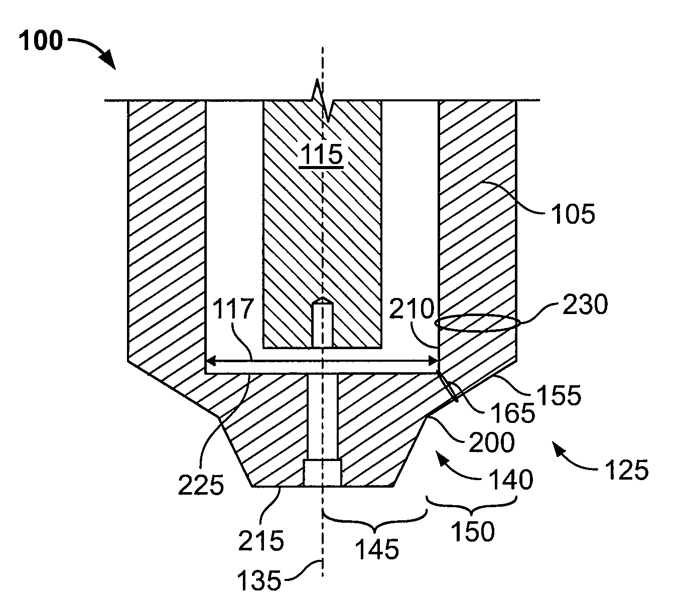
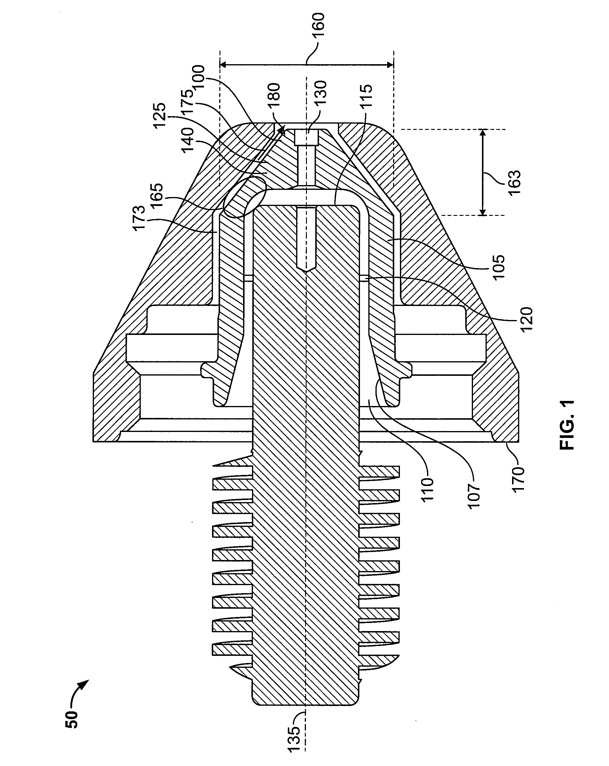
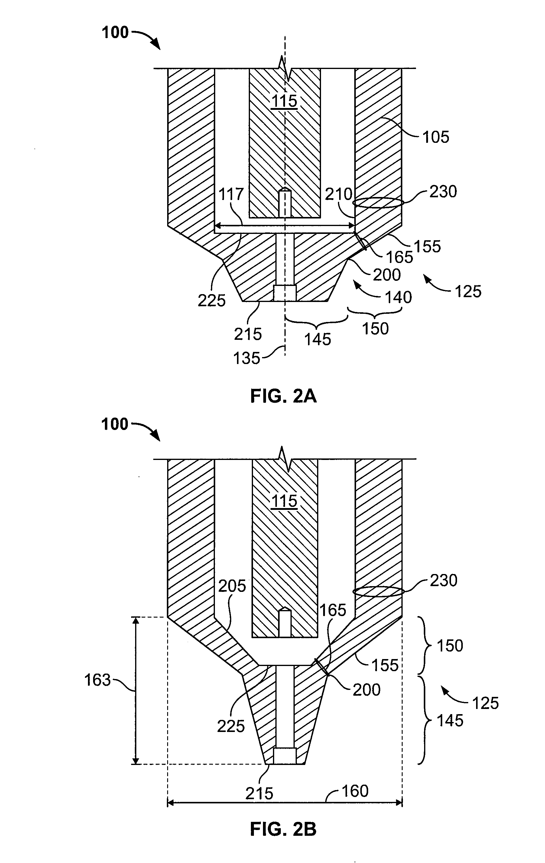
[0054]FIG. 1 illustrates a simplified view of a known gas-cooled torch tip 50. The nozzle 100 includes a substantially cylindrical body 105 having a hollow interior 110 to receive an electrode 115. A swirl ring 120 can be disposed between the electrode 115 and an interior edge 107 of the body 105. A nozzle head 125 is integrally connected to the body 105. The nozzle head 125 includes a shoulder 140 and an exit orifice 130 disposed about a central longitudinal axis 135.

[0055]A shield 170 can be disposed in a spatial relationship with the nozzle 100. The shield 170 defines a channel 173 for flowing a shield gas 175 to cool the nozzle 100 and to minimize material spatter on the nozzle tip 180.

[0056]It was discovered that for a given torch operating current, as the diameter 160 of the nozzle head 125 is decreased, the nozzle 100 lifespan decreases. It was also discovered that as the length 163 to diameter 160 ratio (i.e., the pointiness) of the nozzle head 125 increases, the nozzle 100 ...


PUM

PropertyMeasurementUnit
Angleaaaaaaaaaa
Currentaaaaaaaaaa
Thicknessaaaaaaaaaa

Abstract

A consumable for a plasma arc torch, such as a nozzle, having a body and a head defining a shoulder portion having a frusto-conical portion and a flared portion. The flared portion increases the cross-sectional thickness to provide a greater heat-conduction path for removal of heat generated by a plasma arc, thereby extending consumable life. The frusto-conical portion provides a sharper, pointier nozzle head to simultaneously increase the operator's visibility of the workpiece. Methods of making and using the consumables are also included.

Description

FIELD OF THE INVENTION[0001]This invention relates generally to gas-cooled plasma arc cutting torches, and more particularly to extending the working life of nozzles for gas-cooled torches with an increased shoulder thickness to decrease the thermal wear rate.BACKGROUND[0002]Welding and plasma arc torches are widely used in the welding, cutting and marking of materials. A plasma torch generally includes an electrode and a nozzle having a central exit orifice mounted within a torch body, electrical connections, passages for cooling, passages for arc control fluids (e.g., plasma gas), and a power supply. Optionally, a swirl ring is employed to control fluid flow patterns in the plasma chamber formed between the electrode and nozzle. The torch produces a plasma arc, a constricted ionized jet of a gas with high temperature and high momentum. Gases used in the torch can be non-reactive (e.g., argon or nitrogen) or reactive (e.g., oxygen or air). In operation, a pilot arc is first generat...

Claims


Application Information

Patent Timeline
IPC IPC(8): H05H1/34B23K10/00B23K9/16
CPCH05H2001/3478H05H1/34H05H1/3478
Inventor DUAN, ZHENG
Owner HYPERTHERM INC
Why Eureka
Try Eureka