
Image forming apparatus

a technology of forming apparatus and forming sheet, which is applied in the direction of thin material processing, article separation, transportation and packaging, etc., can solve the problems of overlapping feeding, increased adsorption force between sheets, and failure of feeding, so as to prevent overlapping feeding and miss-feeding of sheets, the effect of maintaining productivity

Inactive Publication Date: 2009-10-15
CANON KK
View PDF0 Cites 12 Cited by
  • Summary
  • Abstract
  • Description
  • Claims
  • Application Information

AI Technical Summary

Benefits of technology

The present invention provides an image forming apparatus that can prevent sheets from overlapping or missing during feeding, which helps to maintain productivity. This is achieved by detecting the boundaries between sheet bundles and adjusting the feeding condition of the sheet feeding unit accordingly.

Problems solved by technology

With this, overlapping-feeding in which sheets are not separated from each other and two or more sheets are superposed and fed in this state, or miss-feeding (feeding failure) in which a sheet is not fed by the separating mechanism may be generated in some cases
Especially when a new sheet bundle is added to a sheet bundle which is stored in a cassette, this overlapping-feeding is prone to be generated due to extraneous matter or difference in water content of sheets around a boundary between the previously stored sheet bundle and the newly added sheet bundle.
Further, sheets having high smoothness called art paper or coated paper used for color printing are crushed near a boundary between sheet bundles and it becomes difficult for air to enter between the sheets, adsorption force between the sheets is increased, and the overlapping-feeding is prone to be generated near the boundary between the sheet bundles.
If the overlapping-feeding or miss-feeding of sheets is generated, it is necessary to stop the image forming apparatus to take out the overlapping-fed sheet or miss-fed sheet, and the productivity is deteriorated correspondingly.
Therefore, even if the nip pressure of the separating mechanism is adjusted to solve the overlapping-feeding, although it is possible to prevent the overlapping-feeding from being generated from the next sheet, the already generated overlapping-feeding of sheet can not be solved.
Therefore, this proposal is not suitable for overlapping-feeding caused due to change in temporarily surface states of sheets.
That is, a problem such as the overlapping-feeding of sheets which is prone to be generated in a boundary between sheet bundles can not be solved, and it is difficult to maintain high productivity.

Method used


Image

  • Image forming apparatus
  • Image forming apparatus
  • Image forming apparatus

Examples


embodiment 1

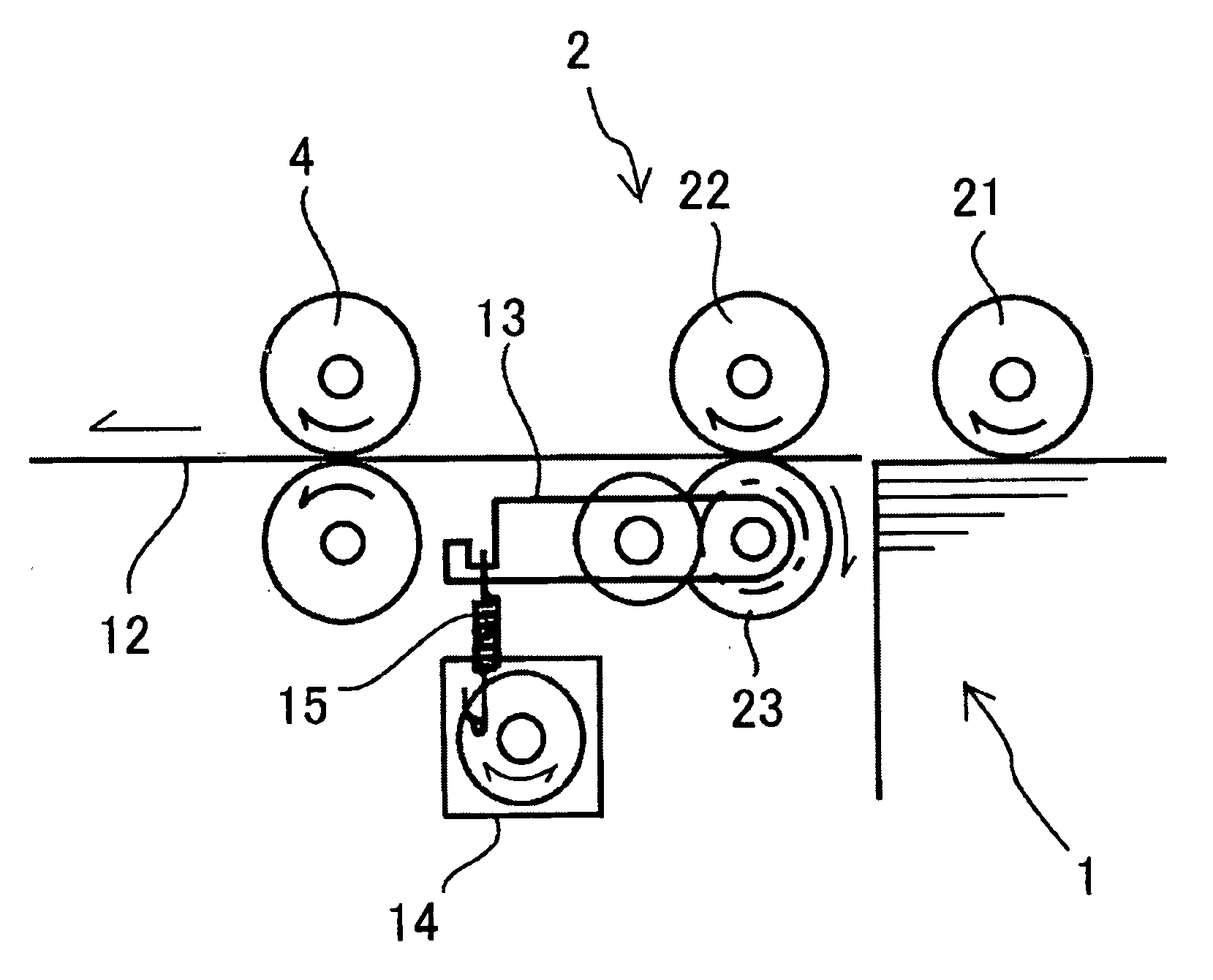
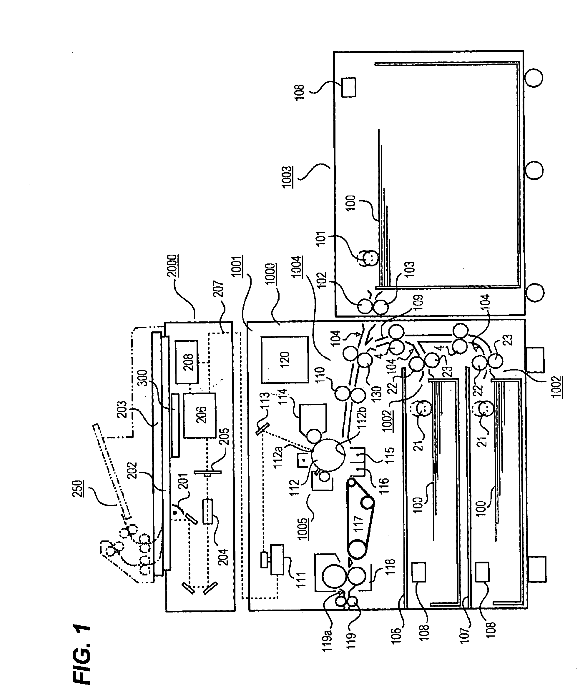
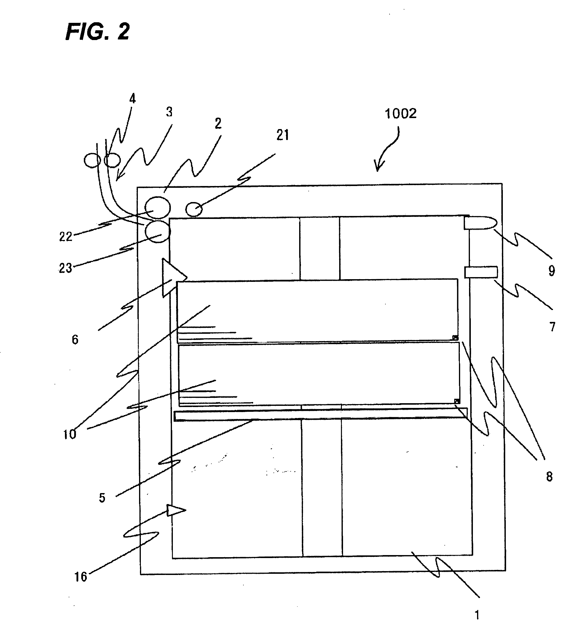
[0031]FIG. 1 is a vertical sectional view illustrating the entire structure of an image forming apparatus according to a first embodiment of the present invention. FIG. 2 is a schematic diagram illustrating a structure of a sheet feeding apparatus illustrated in FIG. 1. FIG. 3 is a diagram illustrating a structure of sheet feeding unit illustrated in FIG. 2.

[0032]A printer 1000 illustrated in FIG. 1 includes a printer body 1001 and a scanner 2000 disposed on an upper surface of the printer body 1001.

[0033]The scanner 2000 reads an image on an original The scanner 2000 includes a scanning optical light source 201, a platen glass 202 and an opening / closing original pressure plate 203. The scanner 2000 further includes a lens 204, a light receiving element 205 (photoelectric conversion), an image processing portion 206, and a memory 208 which stores an image processing signal processed by the image processing portion 206.

[0034]When an original is to be read, the original (not illustrat...

second embodiment

[0089]FIG. 7 schematically illustrates a structure of a sheet feeding apparatus according to a second embodiment. In the second embodiment, the position of the sheet bundle side surface marking unit 7 which is fixed in the first embodiment is provided such that the unit 7 can be lifted and lowered along the stacking direction of sheets. Portions of the second embodiment which are different from the first embodiment will be described in detail, and description of the same structure as that of the first embodiment will be omitted.

[0090]If the sheet storage case 1 is opened to add sheets, the stack tray 5 is lowered by the motor 32, and the stack tray 5 is lowered to a lower limit of the sheet storage case 1 by a lower limit position detection sensor (not illustrated) and stops. The sheet bundle side surface marking unit 7 of this embodiment can be lifted and lowered by lifting / lowering unit 11. The lifting / lowering unit 11 includes a pulley, a wire and a motor, the wire is wound or re...

third embodiment

[0094]In a third embodiment, the sheet bundle side surface marking unit 7 is not used as the sheet bundle boundary detecting unit, the position of the sheet boundary is previously stored, and whenever sheet 12 is fed, the number of sheets is counted and the sheet boundary is detected. Portions of the third embodiment which are different from the first embodiment will be described in detail, and description of the same structure as that of the first embodiment will be omitted.

[0095]In FIG. 8, a control apparatus 30 includes a CPU 31, photo-interrupters 35 and 37 and a numeric keypad 40 are connected to the control apparatus 30, and signals from the photo-interrupters 35 and 37 and the numeric keypad 40 are input to the control apparatus 30. The control apparatus 30 and the magnetic disk unit 39 are connected to each other so that information can be exchanged therebetween. Motors 32 and 33 are connected to the control apparatus 30, and the motors 32 and 33 are controlled based on info...


PUM


Abstract

An image forming apparatus includes sheet bundle boundary detecting unit which detects a boundary of sheet bundles added to a sheet storage case, and control unit which controls a feeding condition of sheet feeding unit based on a detection result of the sheet bundle boundary detecting unit. With this, overlapping-feeding and miss-feeding at the boundary between the sheet bundles are reliably prevented.

Description

BACKGROUND OF THE INVENTION[0001]1. Field of the Invention[0002]The present invention relates to an image forming apparatus such as a copying machine and a printer having a sheet feeding apparatus which feeds a sheet.[0003]2. Description of the Related Art[0004]A conventional image forming apparatus is provided with a sheet feeding apparatus which feeds a sheet to an image forming portion. Especially in a commercial-use mass-printing image forming apparatus, since a sheet feeding operation to the image forming portion largely influences the productivity (the number of sheets to be printed per unit time), it is extremely important to stably and reliably feed sheets by the sheet feeding apparatus.[0005]In separating mechanisms in the sheet feeding apparatuses which enhance the productivity and reliably feed sheets, retard separating systems are widely used. The retard separating system feeds stacked sheets by a pickup roller, separates the sheets one sheet by one sheet and conveys the...

Claims


Application Information

Patent Timeline
Patent Type & Authority Applications(United States)
IPC IPC(8): B65H5/06
CPCB65H7/18B65H2405/15B65H2511/20B65H2511/30B65H2511/414B65H2511/512B65H2513/10B65H2515/30B65H2701/18267B65H2801/06B65H2220/02B65H2220/01
Inventor KOIZUMI, TAKUMAKATO, DAIJIROOYAMA, KIYOSHI
Owner CANON KK
Learn More