Control device for interleaved converters, a system of interleaved converters and related control method

Active Publication Date: 2009-10-15
STMICROELECTRONICS SRL +1
View PDF10 Cites 124 Cited by
  • Summary
  • Abstract
  • Description
  • Claims
  • Application Information

AI Technical Summary

Benefits of technology

[0031]In view of the state of the art, an embodiment of the present invention provides a control device for a converter structure that overcomes the above mentioned disadvantages.
[0032]According to an embodiment a control device for a switching converter structure comprises at least a first and a second interleaved converter, wherein the control device comprises first means adapted to designate one between the first and the second converter as master and at least the other converter as slave, second means adapted to set a time delay of the operating cycle of the slave converter and third means adapted to synchronize the master and the at the least one slave converter.
[0033]In one embodiment, said first means are adapted to detect the one between the first and the second converter which operates at the lower frequency during at least one cycle of switching and to designate it as master and the at least another converter as slave. In one embodiment, said first means is adapted to measure the switching cycle of the master converter. In one embodiment, said second means are adapted to set a time delay for the slave converter, which is given by a part of the measured master switching cycle, after the beginning of a switching cycle of the master converter which is successive to the designation as master. In one embodiment, said converter structure comprises a plurality of n converters, wherein n is an integer number, said second means being adapted to set a time delay for the slave converters shifting them one after the other by a time equal to 1/n of the master switching cycle after the beginning of a switching cycle of the master converter which is successive to the designation as master. In one embodiment, each one of said first and second interleaved converters comprises an inductance, the operating frequency of the converters depending on the demagnetization of the inductance. In one embodiment, said second means are adapted to set a prefixed time delay of the operating cycle of the slave converter after the beginning of a switching cycle of the master converter which is successive to the designation as master. In one embodime

Problems solved by technology

In one embodiment, the method comprises a phase to send a time-out signal when the first and a second interleaved converter operate at frequenc

Method used


Image

  • Control device for interleaved converters, a system of interleaved converters and related control method
  • Control device for interleaved converters, a system of interleaved converters and related control method
  • Control device for interleaved converters, a system of interleaved converters and related control method

Examples


Embodiment Construction

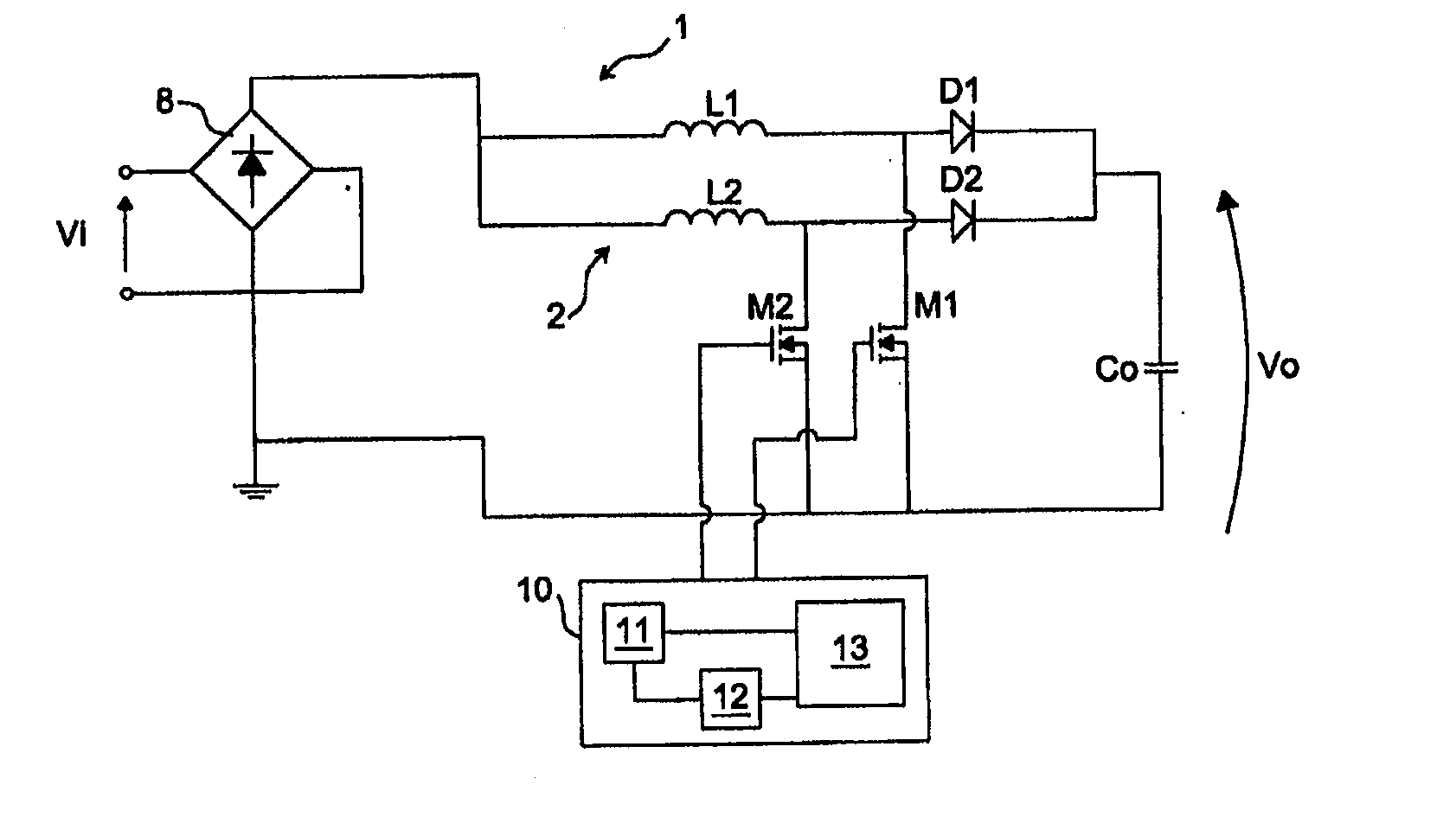
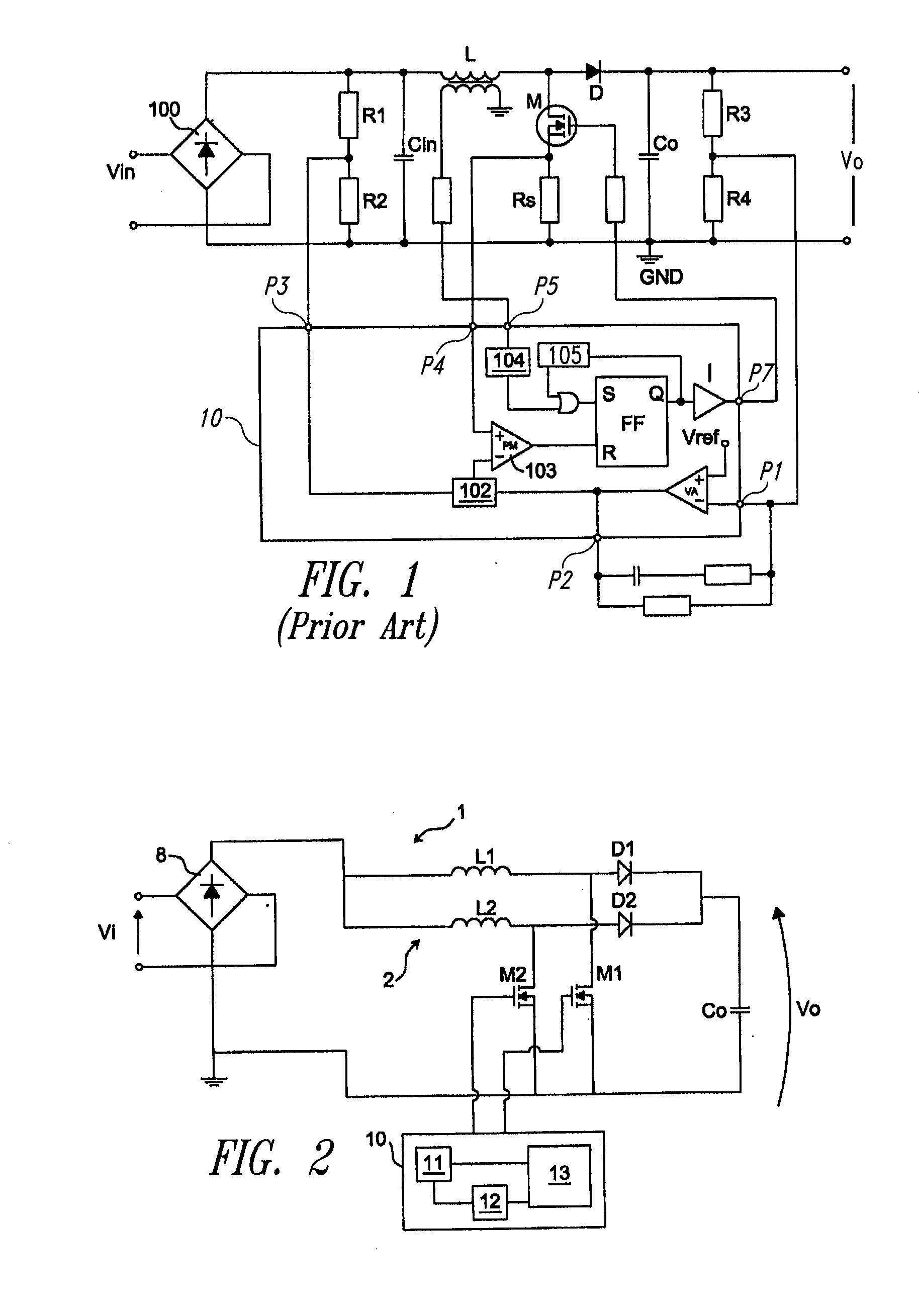
[0048]To facilitate the use of TM PFC beyond the practical limits imposed by heavy filtering requirements it is possible to use multi-phase, or interleaved, converters. Note that the concept of interleaving converters is different from that of paralleling converters. Paralleled converters have in common the input and the output terminals but each of them is a complete, independent unit: separated input front-ends, separated controls, separated output sections; in addition, each converter may have even a different topology. In interleaved converters there is one input front-end, one control and one output section that are shared among all of the individual converters, or stages, which, in addition, have the same topology. Then, when considered all together they form a single entity capable of operating as a stand-alone unit.

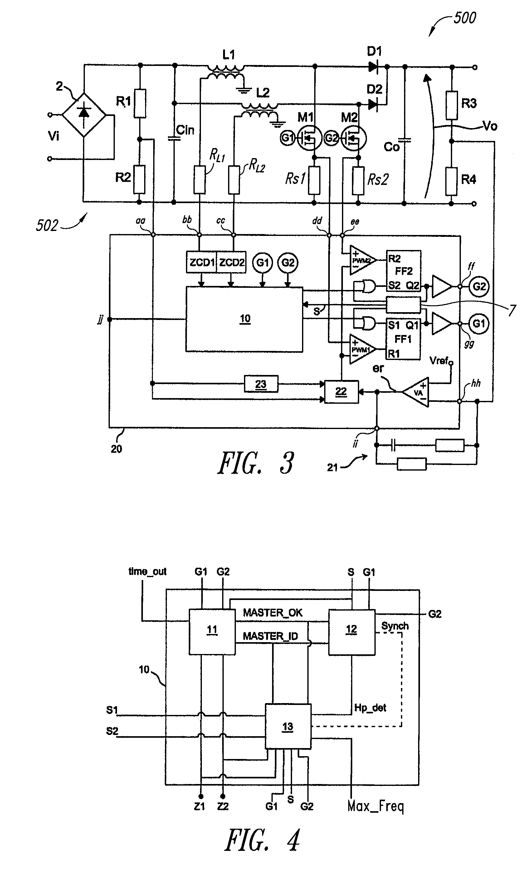
[0049]If controlled with appropriate methodologies, such as properly displacing the phase of the PWM signals controlling each stage, an interleaved converter may ...


PUM


Abstract

Control device for a switching converter structure comprising at least a first and a second interleaved converter, wherein the control device is configured to designate one converter as master and at least the other converter as slave, to set a time delay of the operating cycle of the slave converter and to synchronize the master and the at the least one slave converter.

Description

BACKGROUND[0001]1. Technical Field[0002]The present disclosure refers to a control device for interleaved converters, to a system of interleaved converters and a related control method.[0003]2. Description of the Related Art[0004]Switch-mode Power Supplies (SMPS) which operate off the public distribution power line, are known as “offline power supplies”. These often comprise switch-mode converters used for the active correction of the input power factor (Power Factor Correctors, PFC). The purpose of a PFC converter is to draw from the power line a current that is essentially sinusoidal and in-phase with the line voltage.[0005]The typical front-end stage of a traditional offline SMPS, made up of a bridge rectifier that receives the ac line voltage at its input and a smoothing / reservoir capacitor connected right across the output of the bridge, produces a non-regulated dc voltage bus with some residual ac component superimposed (ripple). This dc bus will serve as the input for a dc-dc...

Claims


Application Information

Patent Timeline
IPC IPC(8): H02J1/10
CPCH02M2003/1586H02M3/1584H02M1/4225Y02B70/10H02M3/1586
Inventor ADRAGNA, CLAUDIONOVELLI, ALDOBORRELLO, ANTONIOHUBER, LASZLOIRVING, BRIAN T.JOVANOVIC, MILAN M.
Owner STMICROELECTRONICS SRL
Why Eureka
Try Eureka