Multi-Channel Timing Recovery System

a multi-channel timing and recovery system technology, applied in the field of hardware-based multi-channel timing recovery system, can solve the problems of over-design system, limited reception performance, and inability to have exactly the same crystal oscillator frequency on both the central office and the customer premises, so as to achieve accurate phase computation of each tone phase and minimum phase jitter noise

Active Publication Date: 2009-10-15
TRIDUCTOR TECH SUZHOU
View PDF5 Cites 12 Cited by
  • Summary
  • Abstract
  • Description
  • Claims
  • Application Information

AI Technical Summary

Benefits of technology

[0008]The present invention defines and implements a novel multi-channel timing recovery scheme that utilizes a shared CORDIC (Coordinate-Rotation Digital Computer) to accurately compute the phase for each tone. Then a hardware-based linear combiner module is used to reconstruct the best phase estimate from multiple phase measurements. The firmware monitors the noise variance for the pilot tones and determines the co

Problems solved by technology

Otherwise, the receiver performance will be limited by the poor timing recovery response.
It is impossible to have the exactly same crystal oscillator frequency on both the central office and the customer premises.
An over-designed system could waste the system cost including hardware and firmware.
An under-designed system could limit the overall system performance.
One important factor that affects the timing recovery system performance is the measurement noise.
For a single pilot tone scheme, the performance wil

Method used


Image

  • Multi-Channel Timing Recovery System
  • Multi-Channel Timing Recovery System
  • Multi-Channel Timing Recovery System

Examples


Embodiment Construction

Timing Recovery Hardware Architecture Diagram

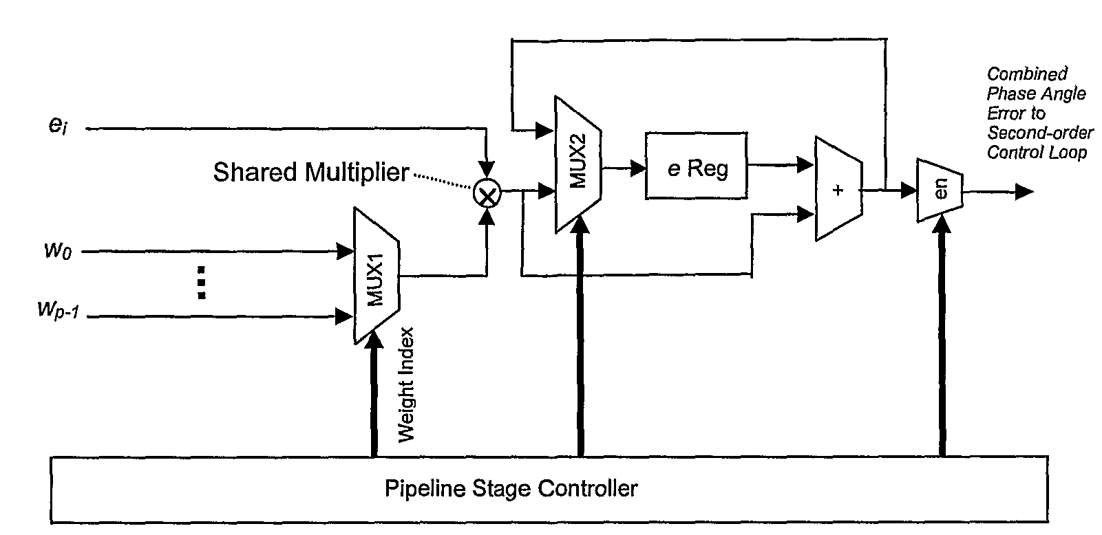
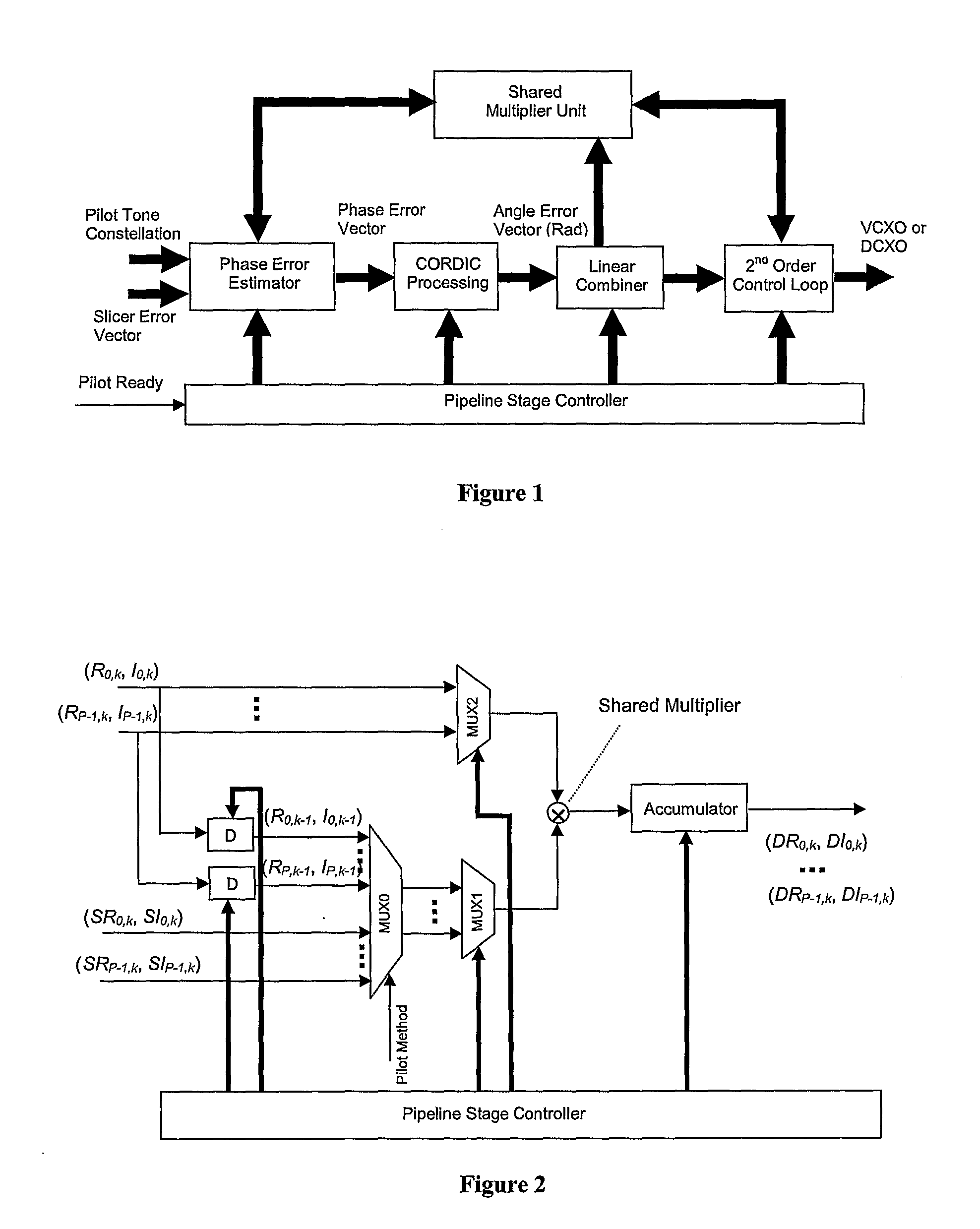
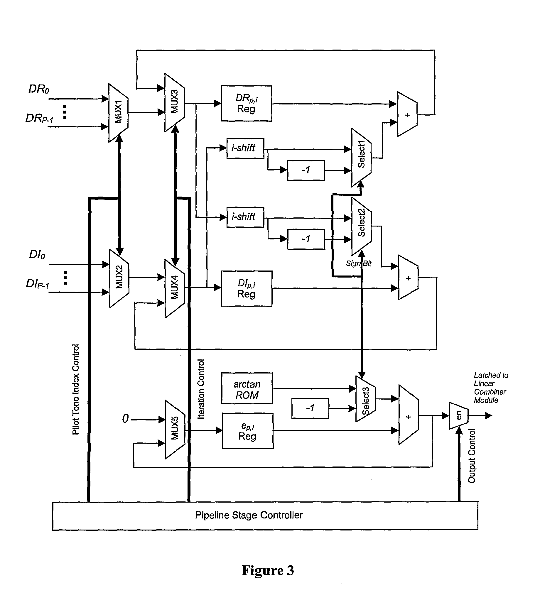
[0017]In our timing recovery system design, we carefully identify the boundary between the hardware and firmware to achieve an optimal solution in terms of hardware cost and firmware speed requirement. FIG. 1 shows the top functional diagram of our timing recovery system design. In our design, based on the firmware configuration, two types of data are required. For reference-based pilot recovery, the pilot constellations (complex values in frequency domain after FFT) are needed. For decision-driven pilot recovery, the slice error values (complex values given by slicer in demodulator) are required. The phase error estimator block processes the raw data of either pilot constellations or slice errors to produce the pilot phase error vector. Then the vector is passed to the cordic processing module to generate exact angle error vector in radius. The angle error vector is combined in the linear combiner module to increase the accuracy of phase...


PUM


Abstract

The present invention discloses a novel multi-channel timing recovery scheme that utilizes a shared CORDIC to accurately compute the phase for each tone. Then a hardware-based linear combiner module is used to reconstruct the best phase estimate from multiple phase measurements. The firmware monitors the noise variance for the pilot tones and determines the corresponding weight for each tone to ensure that the minimum phase jitter noise is achieved through the linear combiner. Then a hardware-based second-order timing recovery control loop generates the frequency reference signal for VCXO or DCXO. A single sequentially controlled multiplier is used for all multiplications in the control loop.

Description

CROSS-REFERENCE TO RELATED APPLICATION[0001]The present application claims the benefit of provisional application No. 60 / 753,616 filed Dec. 23, 2005, the content of which is hereby incorporated by reference in its entirety.FIELD OF THE INVENTION[0002]The present invention relates to a timing recovery system, more particularly to a hardware-based multi-channel timing recovery system with CORDIC processing.BACKGROUND OF THE INVENTION[0003]Timing recovery is a very important receiver function for DMT-based VDSL2 systems. It is vital to design a good timing recovery system to suppress the jitter noise to a level that is comparable to the receiver noise in the loop. Otherwise, the receiver performance will be limited by the poor timing recovery response. In DMT-based systems, single or multiple frequency tones are used as pilot tones that embed the timing phase signals. The timing recovery module reconstructs the phase information from the pilot tones, which is used as reference to the t...

Claims


Application Information

Patent Timeline
IPC IPC(8): H04L7/00
CPCH04L7/02H04L7/0337H04L27/2675H04L27/2679H04L27/2655
Inventor TAN, YAOLONG
Owner TRIDUCTOR TECH SUZHOU
Why Eureka
Try Eureka