General imaging system

a general imaging and system technology, applied in the field of clinical xray imaging devices, can solve the problems of inability to position time-consuming operation for positioning the x-ray emitting means, and inability to achieve the effect of reducing the risk of radiation radiation from the patient,

Inactive Publication Date: 2009-10-15
SHIMADZU CORP
View PDF3 Cites 30 Cited by
  • Summary
  • Abstract
  • Description
  • Claims
  • Application Information

AI Technical Summary

Benefits of technology

[0026]In the case wherein imaging is performed on the same body continuously from different directions, it is possible to perform the imaging continuously without entering the examination room. This functions effectively when, for example, imaging the lung field of the body to be examined from the front and from both sides.

Problems solved by technology

In this series of operations, the operation for positioning the x-ray emitting means is the most time-consuming given that there are a plurality of axes of movement, and that it is necessary to position the x-ray emitting means facing the x-ray detecting means that are hidden by the body being examined.
However, setting these up individually is quite time-consuming because it is not possible to set the imaging conditions without having a substantial amount of knowledge regarding radiation imaging.
In the general imaging system according to the prior art it is not possible to position the x-ray emitting means automatically when examining a new body to be examined.
There are few cases where there are repetitive examinations of the body to be examined, where, in most cases, there is a problem in that the positioning must be done manually.
Additionally, even if there is equipment that automatically positions the height of the x-ray emitting means so as to face the x-ray detecting means, there is a problem in that the automatic positioning must be done after first determining the angle of the x-ray emitting means.

Method used


Image

  • General imaging system
  • General imaging system
  • General imaging system

Examples


Embodiment Construction

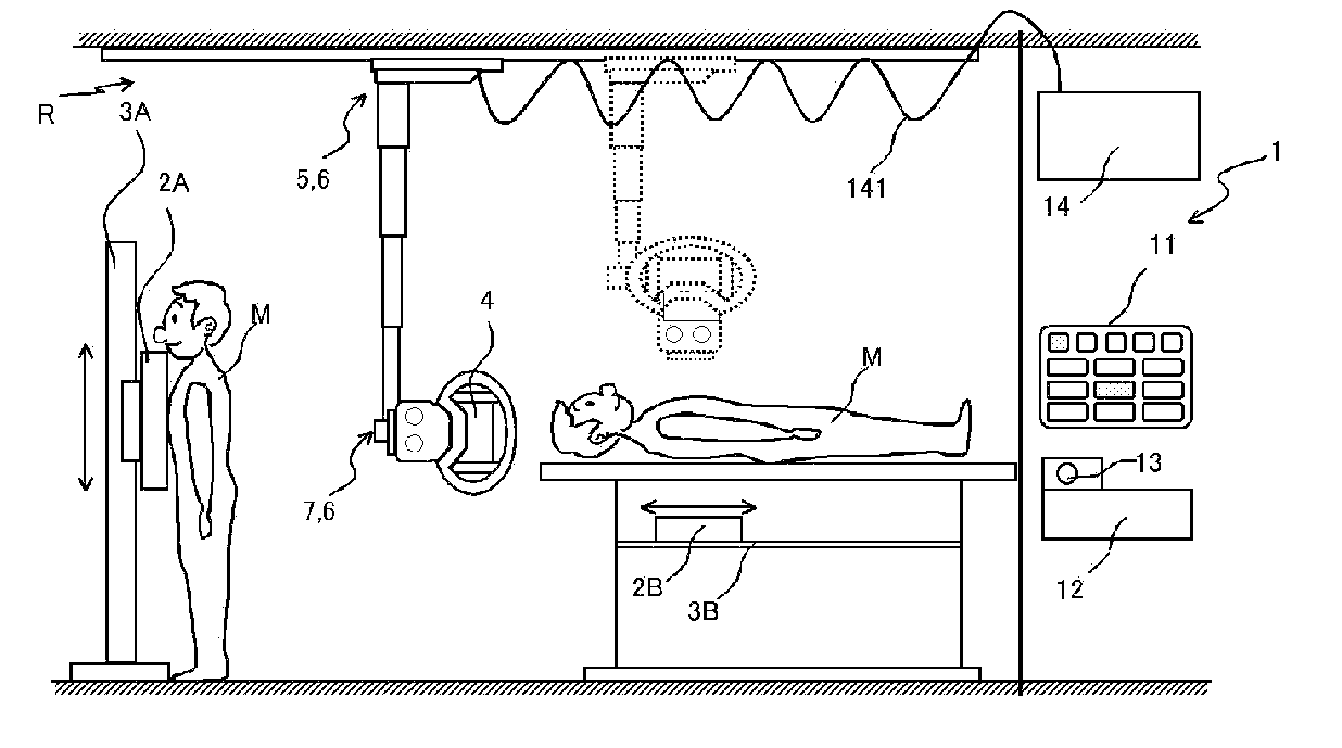
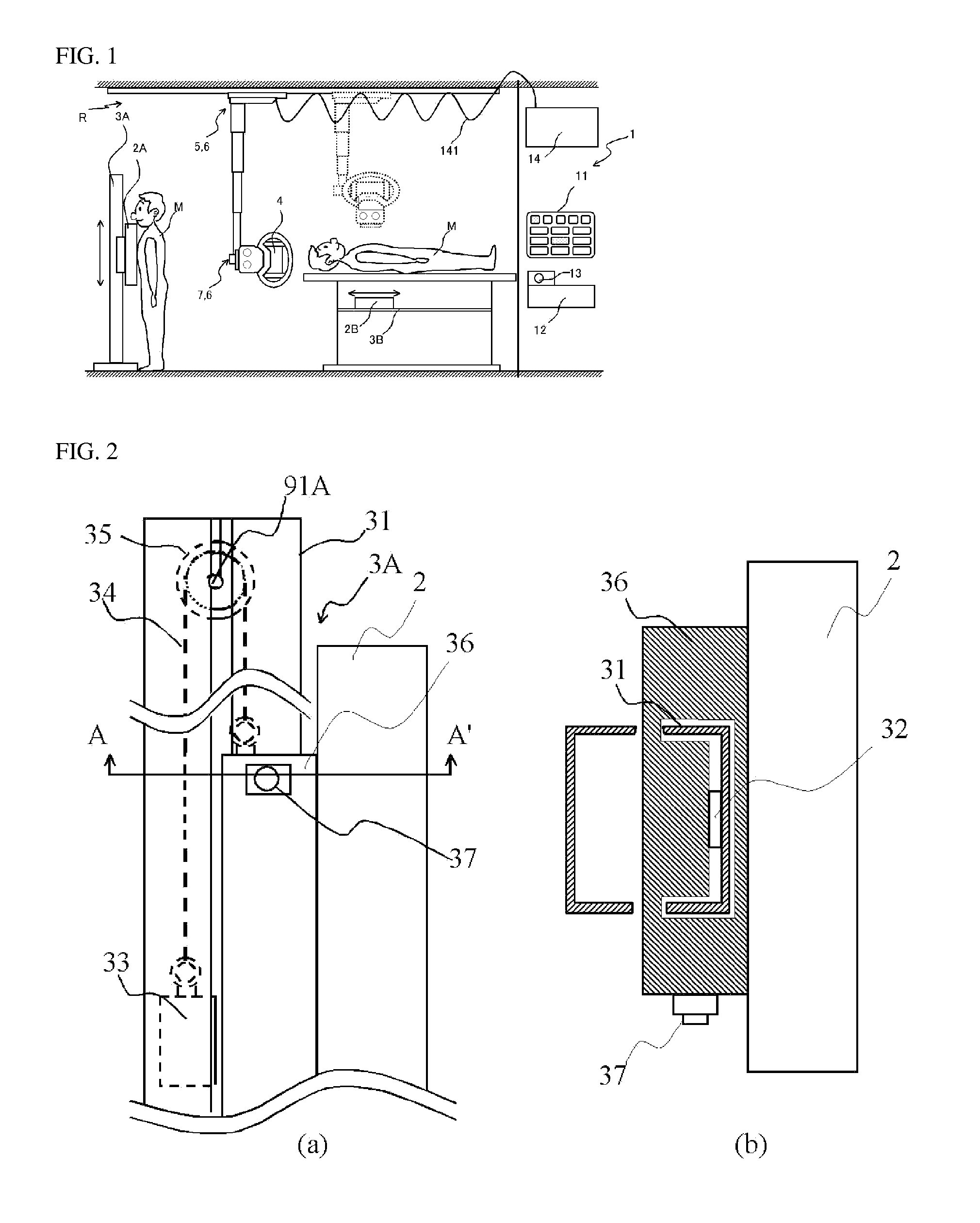
[0033]A summary of a general imaging system according to the present invention is illustrated in FIG. 1. Here the explanation uses, as an example, a system typically known as an erect / supine system.

[0034]When imaging the body to be examined M in the erect state, the imaging is performed by causing the x-ray tube 4, as the x-ray emitting means, to face an FPD (flat panel detector) 2A, as the x-ray detecting means, that is supported movably in the vertical direction relative to the erect stand 3A, as the x-ray detecting means holding means. The FPD 2A has the function of converting the x-rays into an image, where the image is displayed on a monitor, not shown.

[0035]Similarly, when imaging the body to be examined M in the supine state, imaging is performed by causing the x-ray tube 4, as the x-ray emitting means, to face an FPD 2B that is held movably in the lengthwise direction of the body to be examined, relative to the supine table 3B, as the x-ray detecting means holding means.

[003...


PUM


Abstract

To automate positioning operation of an X-ray tube so as to reduce the inspection time. Anatomical program selection means selects a surgery method/imaging object portion so that an imaging condition stored as an anatomical program in advance is called out and set in an X-ray generation device. Here, when an operation switch is pressed, control means moves drive means built in X-ray irradiation means parallel movement holding means and X-ray irradiation means rotation holding means so as to obtain the positional relationship between an X-ray tube and an FPD stored in correspondence with the anatomical program (such as SID and incident angle). The position of the FPD should be matched with the examinee. However, since the positional relationship between the X-ray tube and the FPD is almost constant in accordance with the surgery method/imaging object portion, it is possible to reduce the time required for positioning the X-ray tube by using this configuration.

Description

CROSS REFERENCED TO RELATED APPLICATION[0001]This is a U.S. national phase application under U.S.C. § 371 of International Patent Application No. PCT / JP2007 / 069878, filed Oct. 11, 2007 and claims the benefit of Japanese Application No. 2006-317419, filed Nov. 24, 2006. The International Application was published on May 29, 2008 as International Publication No. WO / 2008 / 062611 under PCT Article 21(2). The contents of the above applications are incorporated herein in their entirety.FIELD OF TECHNOLOGY[0002]The present invention relates to a clinical x-ray imaging device for creating an x-ray image of a body being examined, and in particular, relates to technology for positioning automatically the x-ray emitting means.BACKGROUND OF THE INVENTION[0003]Conventionally, as this type of device there is, for example, a structure wherein x-ray emitting means are suspended so as to be able to move along the ceiling, and where the orientation of the x-ray emitting means can be adjusted. (See, fo...

Claims


Application Information

Patent Timeline
Patent Type & Authority Applications(United States)
IPC IPC(8): H05G1/58H05G1/02A61B6/08
CPCA61B6/4233A61B6/4464A61B6/4476A61B2019/562A61B6/545A61B6/547A61B6/588A61B6/467A61B2034/252
Inventor OKUNO, TOMOHARUKAWANO, MASAHIROKATO, MIKIHIKOYAMASHITA, NOBORUHIRATA, GORO
Owner SHIMADZU CORP
Why Eureka
Try Eureka