
Transdermal patch system

a technology of transdermal patch and patch system, which is applied in the direction of bandages, dressings, therapy, etc., can solve the problems of ineffectiveness, difficult control of infusion rate, and limited iontophoresis-based drug delivery, so as to maintain awareness and remain alert

Inactive Publication Date: 2009-10-15
LOS GATOS RES
View PDF47 Cites 230 Cited by
  • Summary
  • Abstract
  • Description
  • Claims
  • Application Information

AI Technical Summary

Benefits of technology

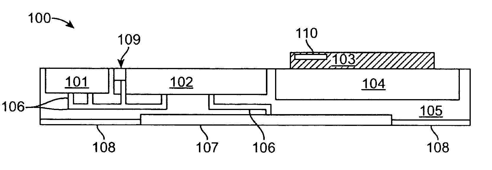
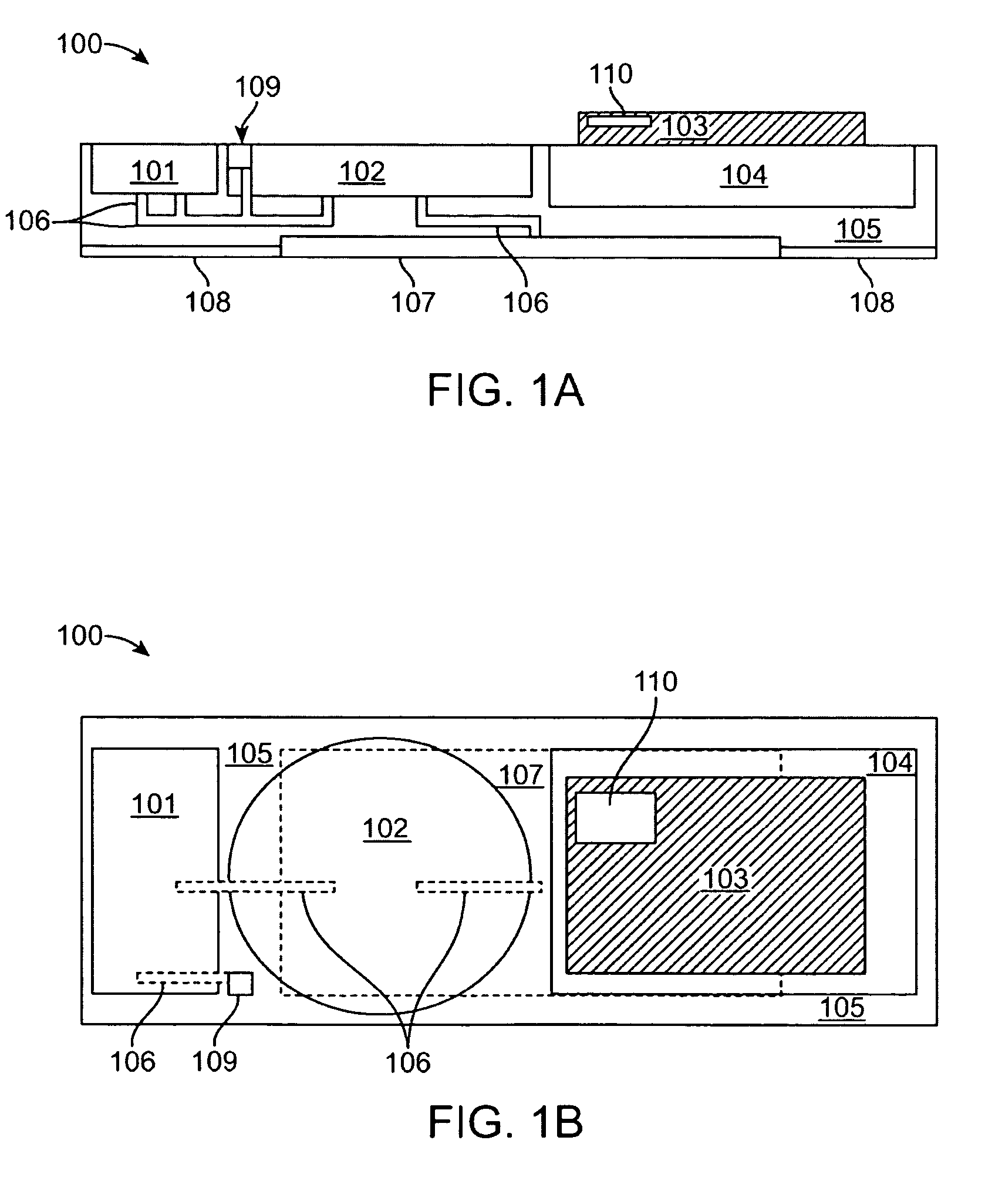
[0011]Aside from the control circuitry, the microchannels fluidly coupling the various features, such as the reservoir, pump, and microporous membrane may be formed directly within or along the housing and sized to have cross-sectional dimensions ranging anywhere from 1 micron to 5000 microns and lengths varying anywhere from 1 millimeter to 1 meter or longer. Because of their size, the microchannels may facilitate the passage of fluids, such as through capillary action, such that fluid delivery through the channels is consistent regardless of the orientation or angle of the assembly. Moreover, the microchannels may also help to inhibit or prevent the formation of bubbles within the channels such that drug delivery may be metered consistently to the patient.
[0012]In yet another variation of the programmable patch or pump assembly, an elongate microchannel may be utilized as the fluid reservoir rather than a single box-like chamber. The microchannel reservoir may be configured into an elongate channel having a cross-sectional dimension ranging anywhere from 1 micron to 1000 microns and a length varying anywhere from 1 millimeter to 1 meter or longer which is looped into an alternating (or “back-and-forth”) pattern which extends over the width and / or length of patch or pump housing. Because of its micrometer scale, the microchannel reservoir reduces the degrees of freedom for liquid movement and constrains the liquid contained within. As a result, altering the orientation of microchannel reservoir in space (three dimensions), such as by rotation or vibration is much less likely to result in the formation of bubbles, gaps, or voids within the contained liquid that may interfere with pumping.
[0014]Use of a microchannel as the drug formulation reservoir may also allow for different types of pump configurations. Rather than using a pump to extract liquid from the microchannel reservoir and pumping it out to ultimately reach a user's skin, an air or gas pump can instead be used to push the liquid down the length of the microchannel reservoir to be ultimately deposited on the user's skin. In a conventional transdermal patch with a single reservoir, use of an air pump is difficult because changing an orientation of the patch or pump may result in pushing air rather than the drug formulation towards the user's skin. This may be avoided because the microchannel reservoir inhibits or prevents bubbles of air from sliding past fluid already contained within the microchannel. Rather, the contained fluid is pushed distally through the microchannel as more air is pumped behind it.
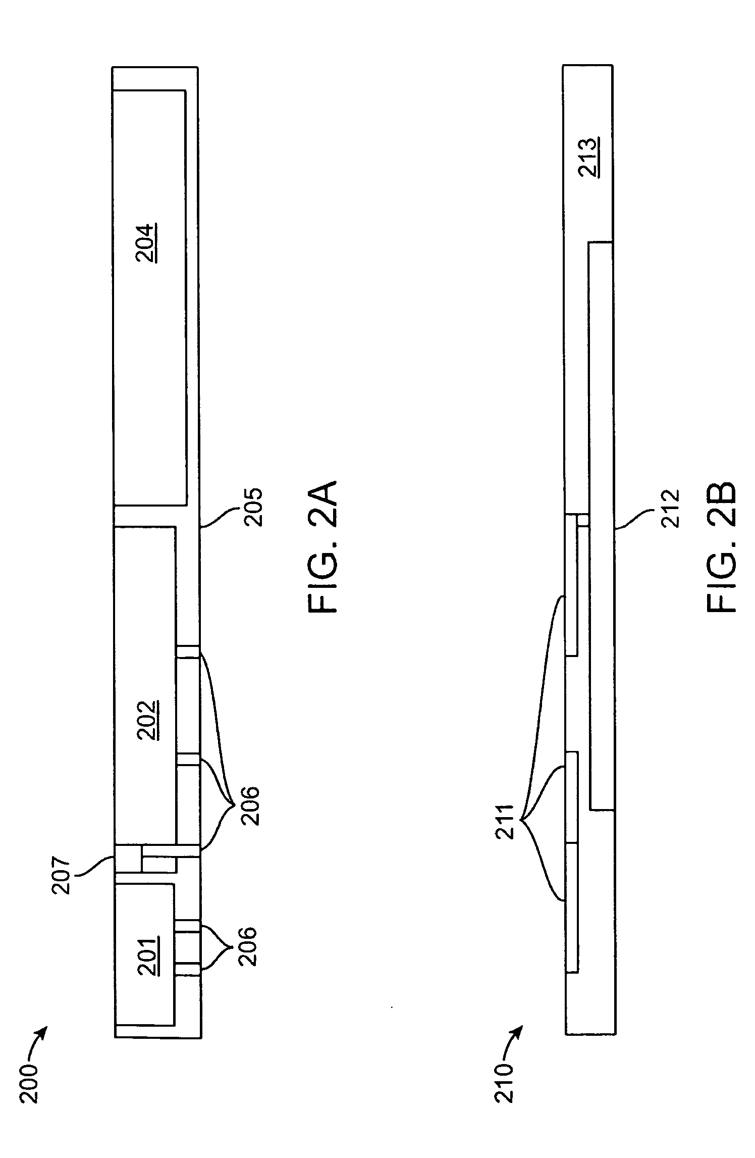
[0015]In yet another variation, the microchannel reservoir may be completely removable from the patch or pump. The microchannel reservoir can reside in a removable package or cartridge which may be inserted securely within an interface or receiving channel defined within the housing. Once the reservoir has been depleted, it may be refilled or the cartridge may be removed entirely from the housing and replaced with another cartridge without having to remove the housing from the patient's skin.

Problems solved by technology

However, with such patches it can be difficult to control the infusion rate and may or may not be effective depending upon the condition or the patient's skin surface.
Moreover, typical iontophoresis-based drug delivery is limited to certain classes of ionic molecules which exclude a wide variety of medications, particularly drugs having a relatively large molecule size.
However, use of a typical fluid reservoir may be problematic with respect to maintaining the reservoir under pressure to provide adequate flow through the delivery mechanism.
Moreover, fluid reservoirs may be susceptible to the formation of bubbles within the fluid as well as the angle and orientation of the reservoir relative to the patient's body.
Additionally, typical fluid reservoirs may also provide for a number of failure points through which the fluid may leak thus resulting in lowered drug delivery efficiency.

Method used


Image

  • Transdermal patch system
  • Transdermal patch system
  • Transdermal patch system

Examples


Embodiment Construction

[0032]In delivering drugs or agents into a patient body over any extended period of time, a patch or pump apparatus or system may be placed into contact upon a region of the user's skin surface and used to transport the drugs or agents transdermally via a number of mechanisms such as maintaining simple contact of the drugs or agents upon the skin surface for absorption (either with or without chemically enhanced absorption), iontophoresis where an applied electrical current or voltage drives the drugs or agents through the skin, membranes, needles, in-dwelling catheters, etc. The patch or pump may be removably adhered or placed via any number of methods directly upon the user's skin surface, e.g., along the arms, legs, hips, abdomen, etc. For example, a portion of the patch or pump or the entire apparatus may be adhered directly to the skin via a temporary adhesive layer or optionally through direct pressure utilizing a strap or band. Alternatively, the patch or pump may be held or ...


PUM


Abstract

A transdermal patch system configured as a patch or pump assembly may be placed into contact upon a skin surface to transport drugs or agents transdermally via any number of different mechanisms such as microporous membranes, microneedles, in-dwelling catheters, etc. The assembly may enclose or accommodate a reservoir configured as an elongate microchannel to contain the drug or agent suspended in a fluid vehicle. The reservoir may also be fluidly coupled via microchannels to transport the drugs into or against an underlying skin surface as driven or urged via a pump and controlled by an electronic control circuitry which may be programmed to affect any number of treatment regimens.

Description

FIELD OF THE INVENTION[0001]The present invention relates to transdermal patch systems. More particularly, the present invention relates to patch or pump systems or apparatus which may be positioned upon a region of a patient's skin surface and their methods of use to efficiently deliver any number of drug therapies in a controlled manner,BACKGROUND OF THE INVENTION[0002]Transdermal delivery of drugs generally allows one or more pharmaceutical agents to be introduced into a patient's system at a controlled rate through the skin. Drug delivery may be effected via a patch which contains a drug which is applied to the patient's skin. The drug may penetrate the skin surface by various passive or active mechanisms. Examples of passive mechanisms may include simple diffusion or absorption through the skin, osmosis, etc., and some examples of active mechanisms may include introduction through the skin via mechanical insertion through needles, abrasion, etc., or through electrical methods s...

Claims


Application Information

Patent Timeline
IPC IPC(8): A61F13/02A61M35/00
CPCA61M5/141A61M5/14248A61M35/00A61M37/0015A61M2005/1405A61M2005/14208A61N1/303A61M2205/3569A61M2205/3576A61M2205/3592A61M2205/502A61M2205/6054A61M2037/0023A61M35/10
Inventor YAIRI, MICAH B.
Owner LOS GATOS RES
Learn More