Method of manufacturing coil for stator incorporated in rotary electric machine

a technology of rotary electric machines and stators, which is applied in the direction of magnets, windings, magnetic bodies, etc., can solve the problems of difficult to reliably wind up the integrated body about the core member, the plastic deformation of the turn portions is difficult, and the integration body is more difficult to be wound up about the core member. , to achieve the effect of enhancing the productivity of the stator and being easy to accommoda

Active Publication Date: 2009-10-22
DENSO CORP
View PDF40 Cites 22 Cited by
  • Summary
  • Abstract
  • Description
  • Claims
  • Application Information

AI Technical Summary

Benefits of technology

[0013]The present invention has been made in light of the circumstances described above, and has as its object of enabling reliable winding of an integrated body having turn portions, each bent into a staircase shape, about a core member, and of enhancing the accuracy in the alignment and pitch in linear stack portions, as well as the accuracy in the array in staircase portions of the respective turn portions in a wound body, in manufacturing a stator coil for a rotary electric machine by winding up phase windings consisting of continuous windings.

Problems solved by technology

However, the above manufacturing method causes a difficulty, as explained blow, in winding up the integrated body about the core member with the predetermined winding radius.
Since the turn portions bent into the staircase shape are work-hardened due to the plastic deformation, further plastic deformation of the turn portions is difficult by that much corresponding to the degree of the work hardening.
Therefore, it is difficult to reliably wind up the integrated body about a core member, while bending the turn portions so as to have the predetermined winding radius, using plastic deformation.
Moreover, the fact that the shape of each turn portion is complicated by the presence of the staircase portion makes it more difficult for the integrated body to be wound up about the core member.
For this reason, the wound body is likely to suffer from a larger winding radius than a desired dimension, from disarray in the staircase portions in the turn portions, from uneven intervals between adjacent linear stack portions, or from misalignment in the plurality of linear superposition portions in the respective linear stack portions.
When the linear stack portions of such a stator coil are arranged in the respective slots of the stator core, the accuracy may be deteriorated in the alignment of the linear portions in each slot, the intervals (pitch) may become uneven between the linear stack portions in adjacent slots, or the turn portions projected from the end faces of the stator core are likely to interfere with each other.
The deterioration in the alignment accuracy of the linear portions, or the uneven pitch may lead to the deterioration in the slot occupancy in the stator, or to the deterioration in the output of the rotary electric machine using the stator.
In addition, the interference between the turn portions may lead to the increase in the size of the stator.

Method used


Image

  • Method of manufacturing coil for stator incorporated in rotary electric machine
  • Method of manufacturing coil for stator incorporated in rotary electric machine
  • Method of manufacturing coil for stator incorporated in rotary electric machine

Examples


first embodiment

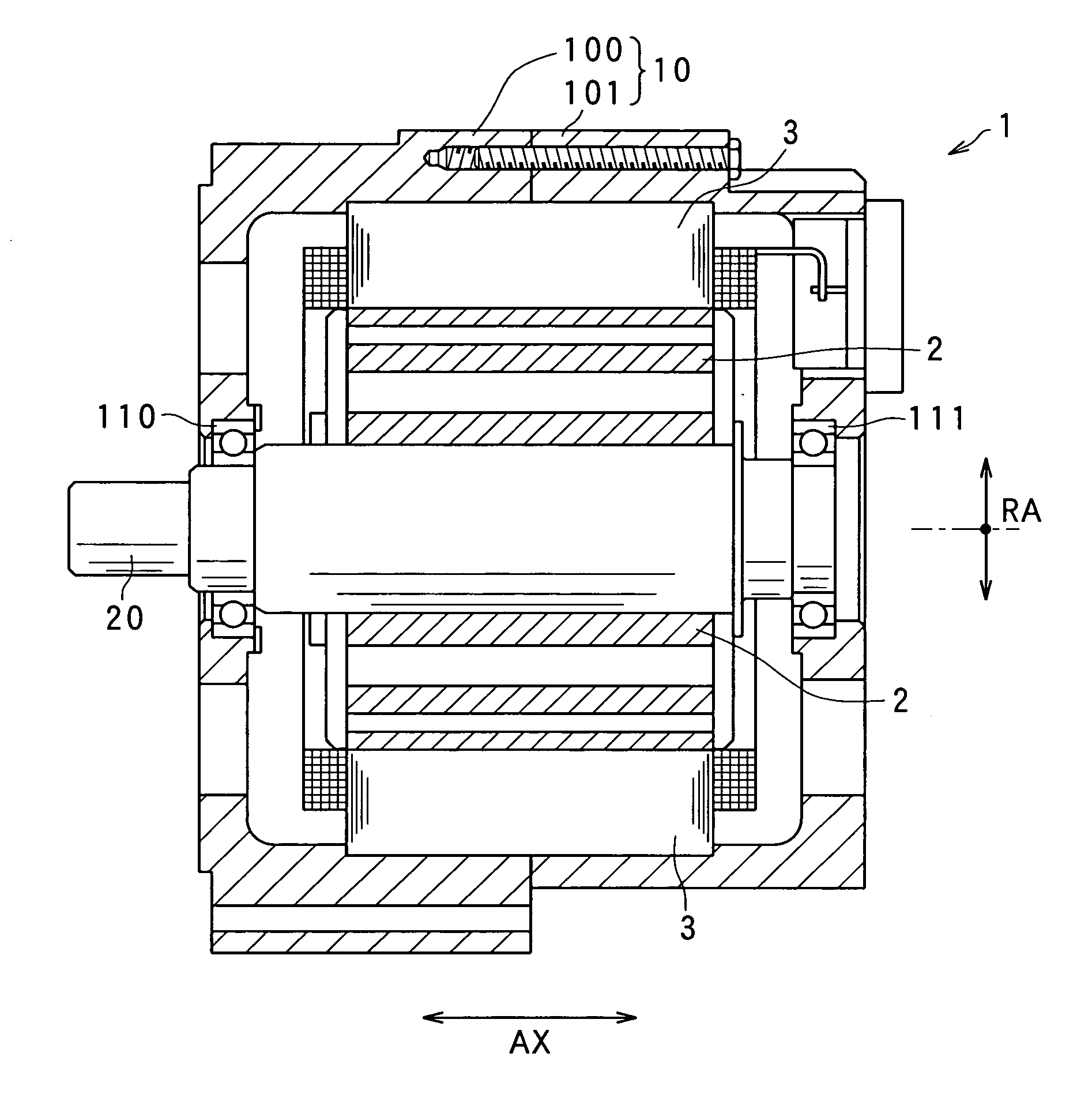
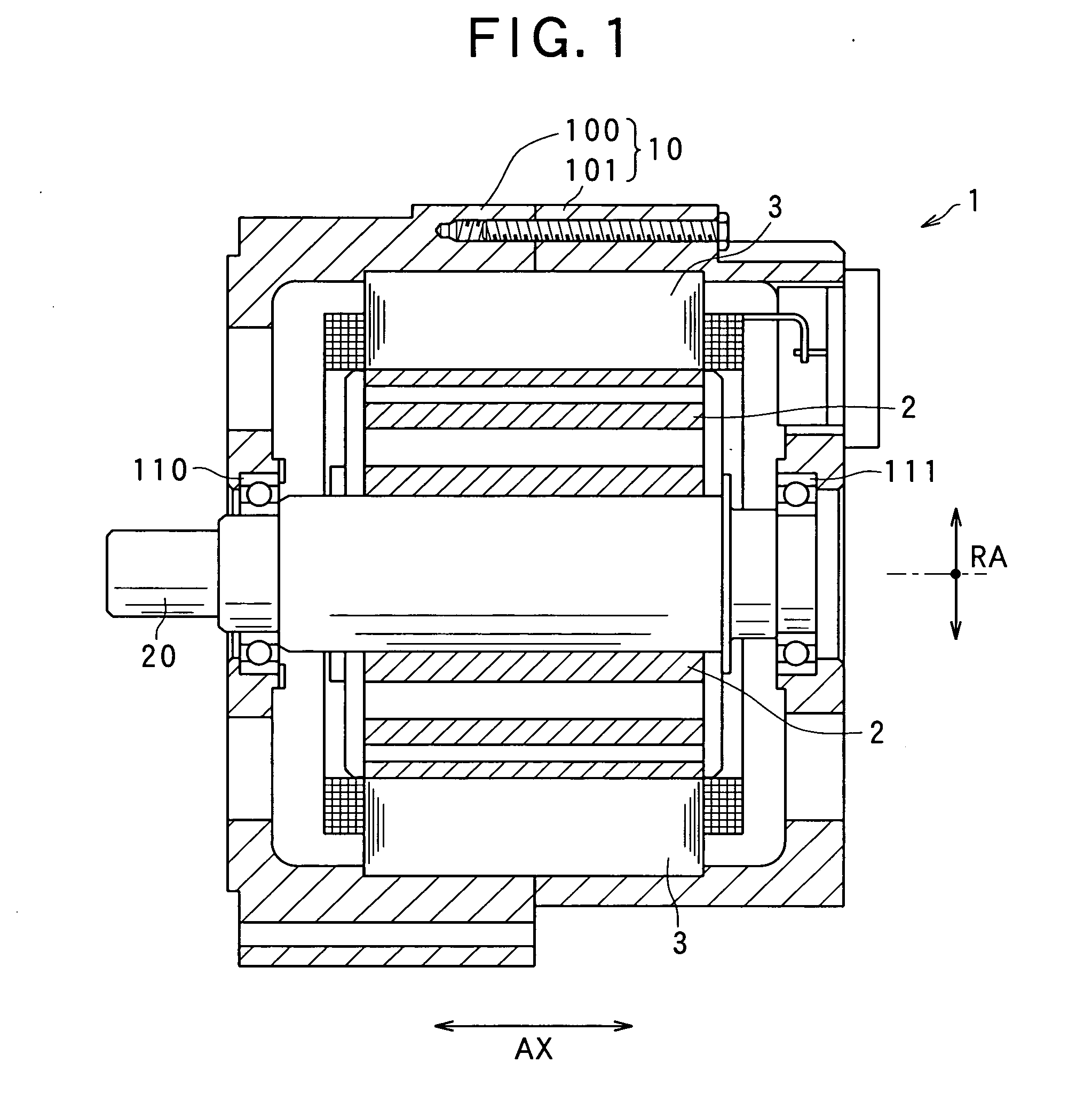
[0056]Referring to FIGS. 1 to 13, hereinafter is described a configuration of a rotary electric machine 1 employing a stator coil obtained through a method for manufacturing a stator coil for an electric rotary machine according to a first embodiment. The rotary electric machine 1 may serve, for example, as an electric motor, an electric generator and a motor generator for vehicles.

[0057]As shown in FIG. 1, the rotary electric machine 1 includes: a housing 10 having a pair of substantially bottomed cylindrical housing members 100, 101 whose opening portions are joined with each other; a rotary shaft 20 rotatably supported by the housing 10 via bearings 110, 111; a rotor 2 secured to the rotary shaft 20; and a stator 3 secured to the housing 10 at a position in the housing 10, where the stator can enclose the rotor 2. In the description of the rotary electric machine 1, the direction along the rotary shaft 20 is referred to as an axial direction AX, the direction that goes around the...

second embodiment

[0133]Referring to FIG. 14, hereinafter is described a method for manufacturing a stator coil for a rotary electric machine, according to a second embodiment. Is should be appreciated that, in the second and the subsequent embodiments, the identical or similar components to those in the first embodiment are given the same reference numerals for the sake of omitting or simplifying explanation.

[0134]The method for manufacturing a stator coil according to the second embodiment shown in FIG. 14 is different from the configuration of the first embodiment in that the configuration of the convex and concave tools 71, 72 as the curve forming unit 7 has been changed.

[0135]Specifically, the convex tool 71 has a convex pressing plate 712 made up such as of an elastically deformable steel leaf. The convex pressing plate 712 has a curved shape that substantially matches the convex curve-forming face 711 of the convex tool 71, to cover the convex curve-forming face 711. The convex pressing plate ...

third embodiment

[0142]Referring to FIGS. 15 and 16, hereinafter is described a method for manufacturing a stator coil for a rotary electric machine, according to a third embodiment.

[0143]FIGS. 15 and 16 illustrate a winding-up step in the method for manufacturing a stator coil according to the third embodiment. This winding-up step is different from that in the above embodiments in that the winding-up step is continuously performed. At the continuous winding-up step, the integrated body 47 is continuously fed to the core member 6 for winding up.

[0144]The plurality of preliminary alignment members 81 are adapted to be movable in the direction in which the integrated body 47 is conveyed, by a pair of feed rollers 85 under the guide of a guide member 83, in conformity with the conveyance direction in a manner of belt conveyor. A preliminary alignment member movement regulating member 84 is provided to control the insertion / withdrawal of the plurality of preliminary alignment members 81, for the gaps 4...


PUM

PropertyMeasurementUnit
thicknessaaaaaaaaaa
thicknessaaaaaaaaaa
electrically conductiveaaaaaaaaaa

Abstract

A method is provided for manufacturing a stator coil for a rotary electric machine, which is formed by winding up a plurality of phase wires. The method includes a shaping step for shaping a plurality of shaped wire members from electrically conductive wires, an integrating step for integrating the plurality of shaped wire members with each other to form an integrated body, and a winding-up step for winding the integrated body about a core member to form a wound body. At the winding-up step, curve forming is performed by plastically deforming turn portions of the integrated body into a curved shape, during conveyance of feeding the integrated body to the core member.

Description

CROSS-REFERENCE TO RELATED APPLICATION[0001]This application is based on and claims the benefit of priority from earlier Japanese Patent Application Nos. 2008-110790 filed on Apr. 21, 2008 and 2009-101261, filed on Apr. 17, 2009, the description of which is incorporated herein by reference.BACKGROUND OF THE INVENTION[0002]1. Technical Field of the Invention[0003]The present invention relates to a method for manufacturing a coil for a stator loaded on a rotary electric machine, and in particular, to a method for manufacturing a coil called a stator coil wound about such a stator.[0004]2. Related Art[0005]In recent years, small size, high power and high quality have been demanded of rotary electric machines, such as electric motors and electric generators. Taking rotary electric machines loaded on vehicles as an example, the space for loading such a rotary electric machine has been reduced more and more, while the output has been required to be more enhanced.[0006]Under such circumsta...

Claims


Application Information

Patent Timeline
Patent Type & Authority Applications(United States)
IPC IPC(8): H02K15/00
CPCH02K15/0478Y10T29/49071Y10T29/49009H02K15/066
Inventor TAKADA, MASAHIROAKIMOTO, AKITOISHIZUKA, ATSUO
Owner DENSO CORP
Why Eureka
Try Eureka