Feeder for a thermoforming machine

a thermoforming machine and feed tube technology, applied in the direction of packaging, packaging bottles, individual articles, etc., can solve the problems of inability to reliably fill the filling tube present there, inability to precisely position the sorting plate with respect to the filling tube of the filling unit, and inability to distribute the products uniformly over its surface, etc., to achieve the effect of compensating manufacturing tolerances, simple relative mechanical adjustment of the hanger device, and positioned very accurately with respect to each other

Inactive Publication Date: 2009-10-22
UHLMANN PAC SYST
View PDF4 Cites 10 Cited by
  • Summary
  • Abstract
  • Description
  • Claims
  • Application Information

AI Technical Summary

Benefits of technology

[0018]It is an object of the invention to provide a feeder, where the desired arrangement of the sorting plate with respect to the filling tubes of the filling unit is to be accomplished more easily, and in addition the requirements on manufacturing tolerances are to be lowered.
[0020]As a result, manufacturing tolerances can be compensated by way of a simple relative mechanical adjustment of the hanger devices, and the sorting plate and the filling tubes can be positioned very accurately with respect to each other. It can thus be guaranteed that the filling unit with the filling tubes is centered precisely with respect to the openings provided for them in the sorting plate, as a result of which the process of sorting the tablets into the filling tubes is realized in optimal fashion. Another advantage is that the different format units can be designed to be hung onto different feeders in the same way, so that maintenance work is simplified, and it becomes easier to refit a feeder with a new format unit.
[0021]According to one exemplary embodiment, the adjusting device is assigned to the first hanger device. Alternatively or in addition, the adjusting device can be assigned to the second hanger device. The assignment of an adjusting device to a hanger device makes it very easy to make the necessary adjustments, and the additional assignment of a second adjusting device to the second hanger device brings about even more improved adjustment possibilities for positioning the filling tubes with respect to the sorting plate.
[0022]The adjusting device preferably comprises an adjusting cam. This makes it possible to make the desired adjustments very easily during the assembly of the feeder, because the hanger devices can be positioned on the base unit once and for all by adjustment of the cam when they are attached.
[0023]It has been found to be advantageous for the first hanger device to be mounted on a first pin, which rests in a first guide groove in the adjusting device assigned to the first hanger device and / or for the second hanger device to be mounted on a second pin, which rests in a second guide groove in the adjusting device assigned to the second hanger device. In particular, both the first and the second hanger devices can each be mounted on two pins. This gives the hanger devices secure support and thus ensures that the sorting plate and the filling unit are securely supported.

Problems solved by technology

The conventional arrangement suffers from the disadvantage that, because of the elastic mounting, it is difficult to position the sorting plate precisely with respect to the filling tubes of the filling unit.
With respect to the pattern of these movements of the sorting plates, however, feeders of this type suffer from several disadvantages, because, although the vertical movements of the sorting plate intended to produce the microjumps do loosen the product “carpet” formed by the products on the sorting plate, they cannot distribute the products uniformly over its surface.
Product items are frequently missing in particular at the edges and in the corners of the sorting plate, so that the filling tubes present there cannot be filled reliably.
This limits the capacity of the system.
This can be compensated to only a limited extent by increasing the quantity of product on the sorting plate, because, although it is true that a sufficient quantity will be available in the disadvantaged zones, piles will form at the same time in the center of the sorting plate, which make it more difficult for the products to drop into the filling tubes.
The disadvantage, however, is that several of these pneumatic piston vibrators are required, and they must be mounted in different positions.
As a result of the mounting of the sorting plate on resilient pads and the design of the pneumatic piston vibrators, precise synchronization is not possible, and the reproducibility of the product distribution is not guaranteed.
The conventional feeders also suffer from the disadvantage that, because of the many small mechanical parts required for the detachable connection of the blocking slide unit to the base unit and for the transmission of movement from the base unit to the blocking slide unit, these conventional feeders are expensive to manufacture.
This method of attachment suffers from the disadvantages that the star handles are not readily accessible, and that it is necessary to deal during the attachment process with many individual parts, which can become lost when the format unit is changed.
In addition, the additional edges make it even more difficult to the clean the base unit and the format unit.
During the production of the conventional blocking slide units, this leads to a first disadvantage that, because of the very small geometric forms and the large number of sockets, a long machine operating time is required to produce them.
During the handling of the conventional blocking slide units, this leads to the second disadvantage that, because the sockets are introduced only into the top surface of the base plate, they make these units very difficult to clean.
Because of their geometry, the corners of these sockets cannot be adequately cleaned, as a result of which residues can remain behind on the base plate.
This arrangement suffers from the disadvantage that the electrical lines must be laid individually into the control panel, because only there can the motors and sensors be connected to the control mechanism.
The electrical lines extend along the filling section, where they can become contaminated with tablet dust.
This increases the amount of cleaning work required.
The external control panel, furthermore, requires additional space next to the blister machine and can under certain conditions interfere with access to the blister machine and make it more difficult to operate the machine.

Method used


Image

  • Feeder for a thermoforming machine
  • Feeder for a thermoforming machine
  • Feeder for a thermoforming machine

Examples


Embodiment Construction

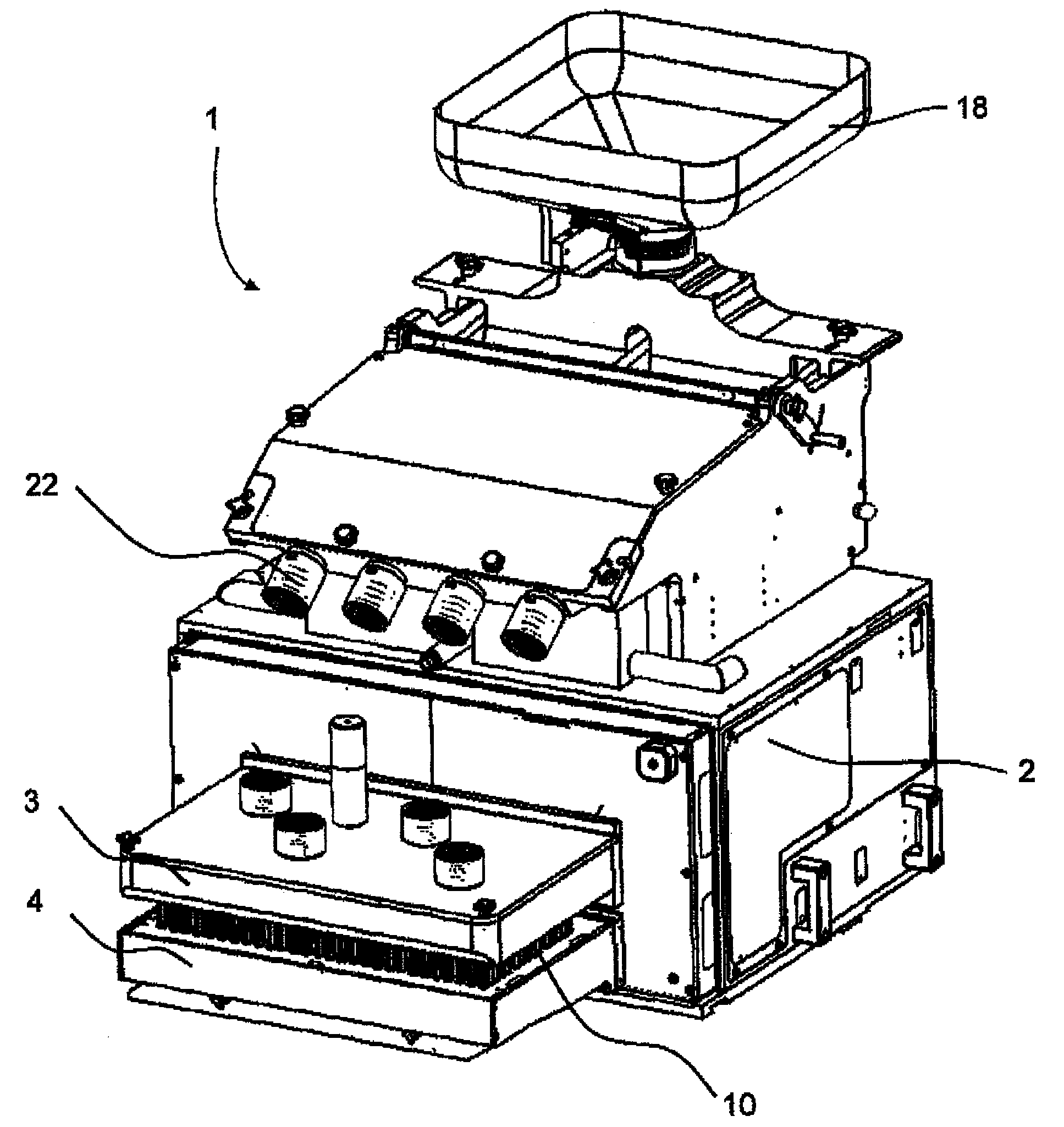
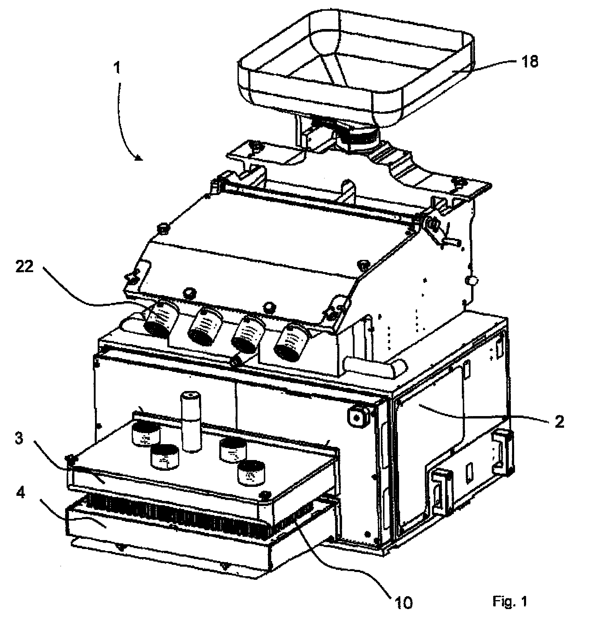
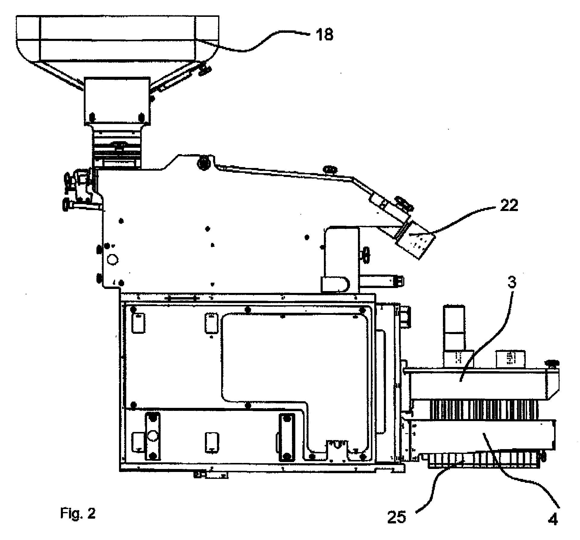
[0059]FIGS. 1-6 show overview diagrams of a feeder 1, whereas the individual assemblies of the feeder 1 and the way in which they work together are described in the following figures.

[0060]The feeder 1 shown in FIGS. 1-6 serves to transfer products, which are made available as bulk material, in a controlled manner into the pockets of a continuously or discontinuously conveyed web of sheeting. This feeder 1 comprises a supply container 18, which holds the products as bulk material, from which container the products are transferred to a sorting plate 3, which sorts the products in such a way that they assume the pattern of the pockets, i.e., the pattern of pockets formed in the web of sheeting. The sorting plate 3 comprises openings 13 (FIG. 4) in the bottom, into which the upper ends of filling tubes 10 project. The product items are sorted into these upper ends. At least one blocking finger, which serves to release specifically the lowermost product item from the filling tube 10, is...


PUM


Abstract

The feeder for tablets, capsules or dragées has a stationary base unit and an exchangeable format unit with a sorting plate for evenly distributing the products and with a filling unit including a number of vertically extending filling tubes having a guiding channel for receiving the tablets, capsules or dragées from the sorting plate, and a blocking slide unit for temporarily blocking the guiding channels of the filling tubes. The base unit has a first hanger device for the sorting plate, a second hanger device for the filling unit, and at least one adjusting device for adjusting the first hanger device relative to the second hanger device.

Description

CROSS-REFERENCE TO RELATED APPLICATIONS[0001]This application claims the benefit of European Patent Application No. EP 08 007 414.9 filed on Apr. 16, 2008, entitled “FEEDER FOR A THERMOFORMING MACHINE” the entire contents of which are incorporated herein by reference.FIELD OF THE INVENTION[0002]The present invention pertains to a feeder for a thermoforming machine.[0003]Thermoforming machines or blister machines, especially in the pharmaceutical area, are used to package products individually, for which purpose, thermoplastic sheet is pulled from a supply roll in the thermoforming machine and sent to a heating station, in which the thermoplastic sheet is heated to the preforming temperature, so that the pockets which are intended to hold the product, which is made available as bulk material, can then be formed in the thermoplastic sheet in a forming station. The pockets in the thermoplastic sheet are usually made in a matrix-like or grid-like pattern and are then filled. Then the th...

Claims


Application Information

Patent Timeline
Patent Type & Authority Applications(United States)
IPC IPC(8): B65B5/06
CPCB65B35/06B65B5/103
Inventor JANS, ERICHGNANN, KURTZULEGER, MARTINREGNER, MARKUSRODI, WOLFGANGLIEBHARDT, JUERGENHESS, CHRISTIAN
Owner UHLMANN PAC SYST
Why Eureka
Try Eureka