Electric ground working vehicle

a ground working vehicle and electric technology, applied in the direction of gas pressure propulsion mounting, non-deflectable wheel steering, electric devices, etc., can solve the problems of difficult to cause the vehicle to travel difficult to turn the vehicle in the direction which the driver wants, and difficult to achieve the effect of more effective safe traveling of the vehicl

Active Publication Date: 2009-10-22
KANZAKI KOKYUKOKI MFG
View PDF15 Cites 47 Cited by
  • Summary
  • Abstract
  • Description
  • Claims
  • Application Information

AI Technical Summary

Benefits of technology

[0015]It is an advantage of the present invention to make it possible to more effectively perform safe traveling of a vehicle even while an acceleration operating element is not operated during traveling, for example, while the vehicle is freewheeling, in a configuration in which a left wheel and a right wheel are independently driven by left and right electric motors, respectively, and an electric ground working vehicle can be turned by a difference in rotating speed of the left and right electric motors, for example.
[0016]An electric ground working vehicle according to the present invention includes: a left wheel and a right wheel, being main driving wheels, which are independently driven by left and right electric motors respectively; at least one caster, being a steering control wheel, which is freely steerable; a working apparatus driven for ground working; an acceleration operating element for performing acceleration instructions; a turn operating element for performing turn instructions; and a control unit; wherein the control unit controls force applied to the wheels, being the brake force or driving force of the wheels so that the rotating speed of a wheel at the inside of a turn, of the left and the right wheels, can be lower than the rotating speed of the wheel at the outside of a turn when the acceleration operating element is not operated during traveling, and turn instructions are inputted from the turn operating element.
[0017]According to the above electric ground working vehicle, since the control unit controls force applied to the wheel, being the brake force or driving force of the wheel, so that the rotating speed of the wheel at the inside of a turn, of the left and the right wheel, can be made lower than the rotating speed of the wheel at the outside of a turn, when the acceleration operating element is not operated during travel and turn instructions are inputted from the turn operating element, the rotating speed of the wheel at the inside of a turn becomes lower than the rotating speed of the wheel at the outside of a turn when the acceleration operating element is not operated during travel. For this reason, the vehicle can be turned even when the acceleration operating element is not operated during travel, which enables more effective performing of safe traveling of a vehicle.
[0018]The electric ground working vehicle according to the present invention includes: a left and a right wheel, being main driving wheels, which are independently drive

Problems solved by technology

Therefore, even if the driver instructs the vehicle to turn through the steering wheel while the vehicle is freewheeling, the riding electric lawnmower vehicle cannot cause the left and the right wheels to generate a difference in rotating speed, so that it is difficult for the vehicle to turn in the direction which the driver wants.
On the other hand, when the riding electric lawnmower vehicle is traveling on a slope with the vehicle rolling, that is, while the vehicle is rolling and tilts to one side, to the left or the right, with an axis which extends in the front to rear direction of the vehicle and passes the center of gravity, gravity acts so that the vehicle slants to one side, namely to the left or the right thereof, so that even if the driver instructs th

Method used


Image

  • Electric ground working vehicle
  • Electric ground working vehicle
  • Electric ground working vehicle

Examples


first embodiment

of the Invention

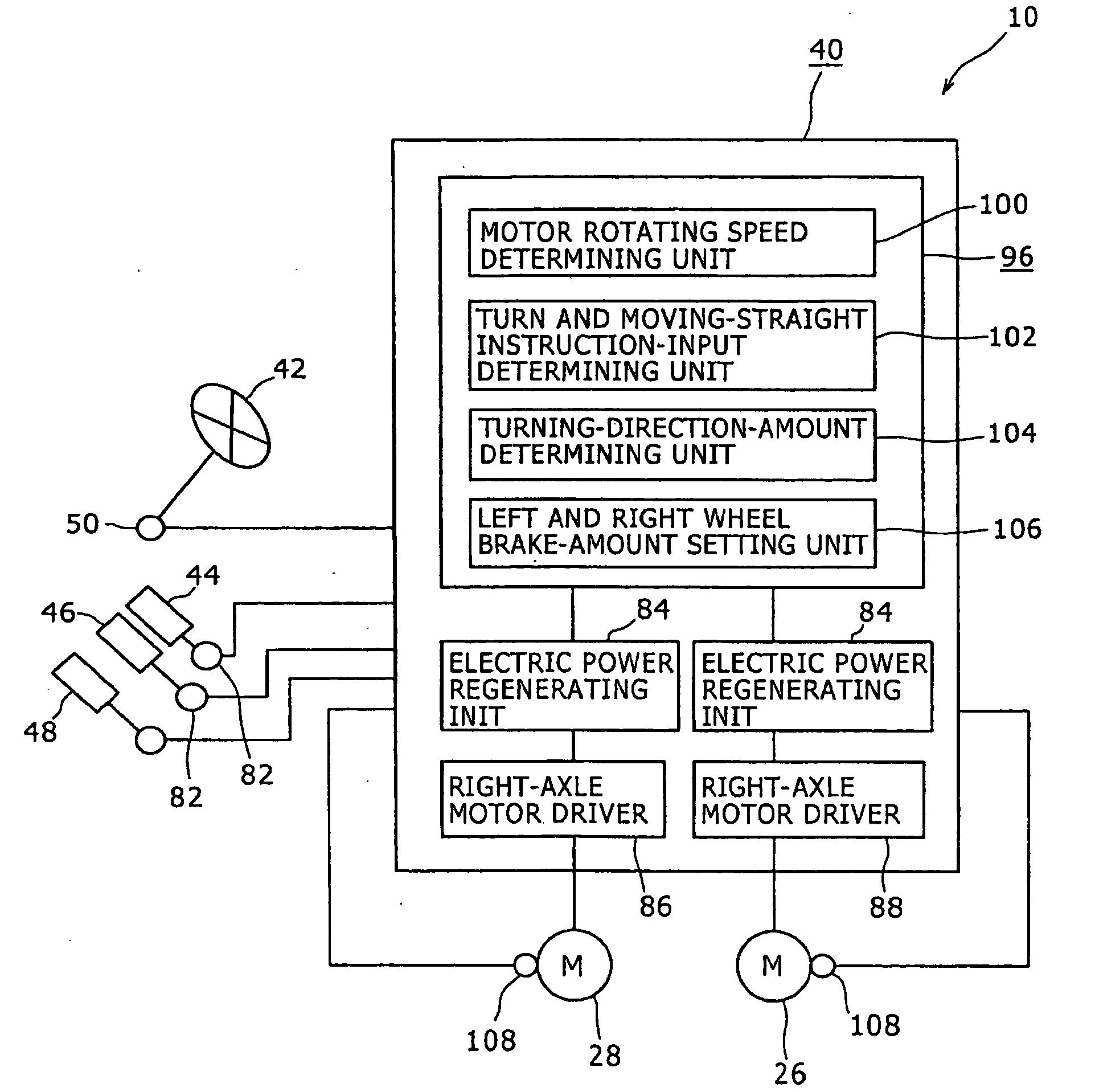
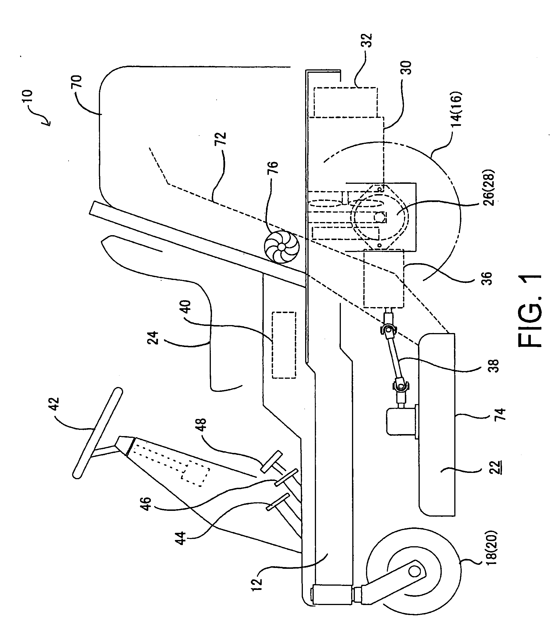
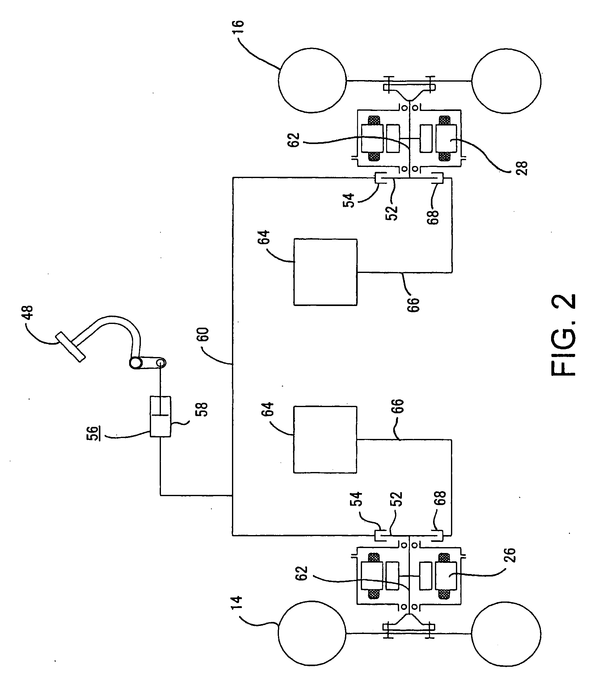
[0055]The embodiment according to the present invention is described in detail below with reference to the drawings. FIGS. 1 to 9 are drawings describing the first embodiment. FIG. 1 is a schematic diagram illustrating a configuration of a lawnmower vehicle, being an electric ground working vehicle according to the present embodiment. FIG. 2 is schematic diagram illustrated one example of a configuration in which a brake controller capable of adjusting the left and the right braking force is provided on a service brake in the present embodiment. FIG. 3 is a block diagram illustrating a basic configuration of components of an electrical system including a controller in the lawnmower vehicle according to the present embodiment. FIG. 4 is a block diagram illustrating the controller in FIG. 3 in detail. FIG. 5 is a flow chart illustrating steps for freewheeling brake control in the present embodiment. FIG. 6 is a chart illustrating a relationship between a rotation angle...

second embodiment

[0118]FIG. 10 is a block diagram illustrating a basic configuration of part of the lawnmower vehicle 10, being an electric ground working vehicle according to a second embodiment of the present invention. In the present embodiment, the lawnmower vehicle 10 includes an initial brake force setting switch 110 which is an initial brake force setting operation unit. The initial brake force setting switch 110 is provided in a position at the periphery of the seat 24 (refer to FIG. 1) where the driver can operate the switch 110 and has an analog or a digital display unit or operating unit. If the initial brake force setting switch 110 is operated, the switch 110 can cause the display unit to display an initial brake force setting. While the driver recognizes the setting value with a dial, the driver can input any initial brake force setting to the controller 40 as a signal. The initial brake force includes the regenerative brake force obtained from the left and the right axle-side electric...

third embodiment

[0126]FIG. 11A is a schematic diagram showing a lawnmower vehicle, being an electric ground working vehicle according to a third embodiment of the present invention, traveling while rolling, viewed from the rear side of the vehicle. FIG. 11B is a schematic diagram viewed from the direction indicated by an arrow “r” illustrated in FIG. 11A. FIG. 12 is a block diagram illustrating a basic configuration of a lawnmower vehicle including a controller according to the present embodiment. FIG. 13 is a flow chart illustrating steps for turn brake control in the present embodiment.

[0127]When the lawnmower vehicle 10 travels on a slope 114 while rolling, that is to say, while the vehicle is rolling and tilts to one side, namely to the left or the right with an axis which extends in the front and the rear direction of the vehicle and passes the center of gravity O as a center, gravity acts in the direction indicated by an arrow S illustrated in FIGS. 11A and 11B. For this reason, the grounding...


PUM


Abstract

There is provided an electric ground working vehicle including a left wheel and a right wheel, at least one caster, a working apparatus, an acceleration operating element for performing acceleration instructions, a turn operating element for performing turn instructions, and a control unit. The left wheel and the right wheel are independently driven by left and right electric motors respectively. The control unit controls a regenerative brake driving unit so that electric power is regenerated from the left and right electric motors to an electric power source unit when the acceleration operating element is not operated during traveling to regeneratively brake the left and right wheels. The control unit controls the brake force of the wheels so that the brake force of the wheel at the inside of a turn, among the left wheel and the right wheel, can be made greater than the brake force of the wheel at the outside of a turn when the acceleration operating element is not operated during traveling and turn instructions are inputted from the turn operating element.

Description

PRIORITY INFORMATION[0001]Japanese Patent Application No. 2008-109360 filed on Apr. 18, 2008 is specified and incorporated herein by reference.BACKGROUND[0002]1. Technical Field[0003]The present invention generally relates to an electric ground working vehicle including left and right wheels independently driven by left and right electric motors respectively, caster wheels being steering control wheels capable of being freely steered, and a working apparatus driven for ground working.[0004]2. Related Art[0005]Hitherto, there has been known a ground working vehicle equipped with a working apparatus driven for ground working such as lawn mowing and cultivation. In such a ground working vehicle, there has been studied an electric ground working vehicle including left and right wheels being main driving wheels independently driven by electric motors respectively, and caster wheels being steering control wheels capable of being freely steered.[0006]For example, as a working vehicle, ther...

Claims


Application Information

Patent Timeline
IPC IPC(8): B62D11/04B60L7/10F16D63/00G06F19/00A01D34/64B60K6/46B60K7/00B60W10/18B60W20/00
CPCA01D34/78Y02T10/7275B60L7/26B60L11/123B60L15/2036B60L2200/40B60L2220/12B60L2220/16B60L2220/44B60L2250/26B62D11/003B62D11/04Y02T10/6217Y02T10/646Y02T10/7077Y02T10/648B60K7/0007Y02T10/72B60L50/61Y02T10/62Y02T10/64Y02T10/70Y02T10/7072
Inventor ISHII, NORIHIROSASAHARA, KENGOEBIHARA, TOMOYUKIKOGA, KAZUNARI
Owner KANZAKI KOKYUKOKI MFG
Why Eureka
Try Eureka