Eureka AIR delivers breakthrough ideas for toughest innovation challenges, trusted by R&D personnel around the world.

Ducted Test Socket

Inactive Publication Date: 2009-10-22
HONEYWELL INT INC
View PDF16 Cites 2 Cited by
  • Summary
  • Abstract
  • Description
  • Claims
  • Application Information

AI Technical Summary

Benefits of technology

[0007]In accordance with the present invention, a ducted test socket for testing a device under test (DUT) is provided. This new and improved test socket can accommodate a large DUT and will improve the airflow through the thermal head to the DUT and out to the shroud.
[0009]The thermal cap can be replaced with a short piece of hose without vent holes, and the buildup of conductive or nonconductive silicone foam rubber around the test socket can be eliminated. The shroud seals directly to the host PB. The PB area needed to form the bottom walls of the channels is minimized to limit PB thermal transfer.
[0010]All air flows down through the air nozzle and hose extension directly into the ducted test socket, where it is channeled around the entire DUT body surface and out four corner outlet ports up into the shroud area. Unlike a standard test socket that interferes with DUT airflow, this ducted test socket greatly enhances DUT airflow. The test socket also insulates the DUT from surrounding air, reducing the thermal load. All of this greatly increases the thermal transfer rate between the forced air and the DUT, resulting in faster temperature transition times and lower air flow rates that reduce the probability of condensation and icing at extended low temperatures. Additional advantages are improved reliability and reduction of cost and schedule associated with DUT temperature testing.
[0011]A variety of air flow ducts could be integrated into a variety of test socket types to simplify the PTFS interface and greatly increase the thermal transfer between its forced air and the DUT.

Problems solved by technology

All of this greatly increases the thermal transfer rate between the forced air and the DUT, resulting in faster temperature transition times and lower air flow rates that reduce the probability of condensation and icing at extended low temperatures.

Method used


Image

  • Ducted Test Socket
  • Ducted Test Socket
  • Ducted Test Socket

Examples


Embodiment Construction

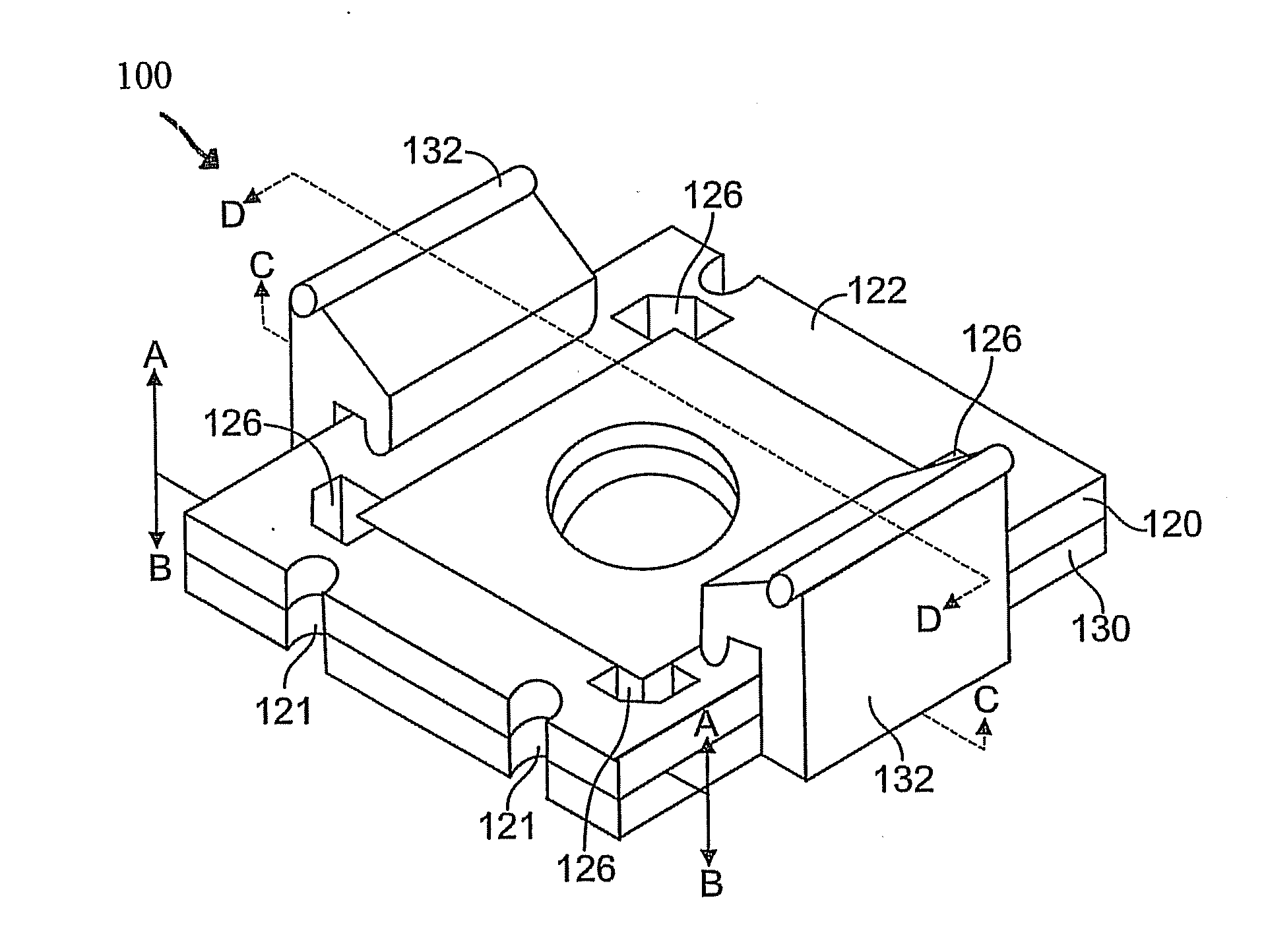
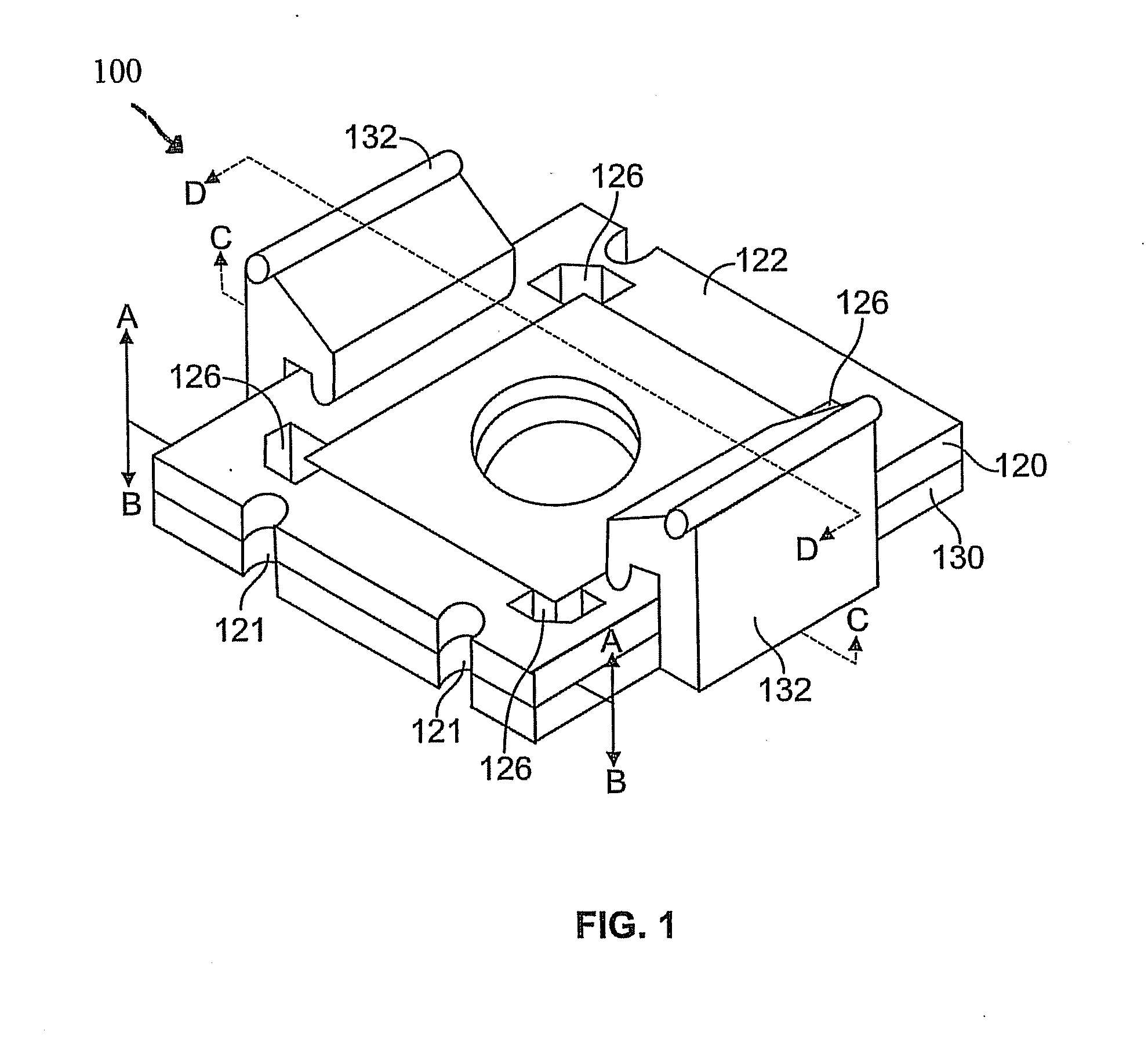
[0020]FIG. 1 depicts a perspective view of a ducted test socket 100 according to one embodiment of the present invention.

[0021]Ducted test socket 100 allows for the testing of a device 110 (not shown). Device 110 may be an integrated circuit. Specifically, device 110 may be a quad flat package (QFP). A QFP is an integrated circuit package with leads extending from each of four sides. Although a QFP typically comprises a flat rectangular or square body with leads on four sides, a multiplicity of designs may exist. For example, device 110 may be a bumpered QFP, which has an array of leads extending from the four sides of the package, and extensions at the four corners to protect the leads against mechanical damages before the unit is soldered. However, ducted test socket 100 may accommodate a number of other terminals.

[0022]Ducted test socket 100 comprises a carrier 120 and a base 130. Base 130 includes a plurality of clamps 132 that rotate to attach the top surface 122 of carrier 120...


PUM


Abstract

A ducted test socket for thermally testing a device under test (DUT) is provided that can accommodate a large DUT and will improve the thermal transfer efficiency between a precision temperature forcing system (PTFS) and the DUT. The ducted test socket comprises a carrier and a base with opposing, mated cavities and holes. These cavities and holes channel airflow around the entire DUT body and out outlet ports.

Description

GOVERNMENT RIGHTS[0001]This invention was made with Government support under Prime Contract Number N00030-05-C-0007 awarded by the United States Navy. The Government may have certain rights in this invention.FIELD[0002]The present invention relates generally to thermal testing of a device under test. More particularly, the present invention relates to a test socket used with a precision temperature forcing system.BACKGROUND[0003]Precision temperature forcing systems (PTFS) provide a low-cost means to thermally test a device under test (DUT). The thermal head of a PTFS is designed for coplanar positioning of the bottom edges of its thermal cap and glass shroud. This usually involves sealing the thermal cap and shroud directly to the host printed board (PB) of the DUT.[0004]A thermal cap attached to the air flow nozzle of the PTFS thermal head directs temperature controlled air directly onto the DUT and then out through its vent holes into the shroud area and eventually out the vent h...

Claims


Application Information

Patent Timeline
IPC IPC(8): G01R31/02
CPCG01R1/0458G01R31/2874G01R31/2863
Inventor EARLE, TERRY R.PURSEL, TIMOTHYSUNDSTROM, LANCE LEROY
Owner HONEYWELL INT INC
Why Eureka
Eureka Blog
Learn More