Pyroelectric sensor with improved abrasion-resistance coating
a technology of pyroelectric sensors and coatings, applied in the field of pyroelectric sensortype thermal pattern sensor, can solve the problems of loss of resolution, inability to obtain satisfactory contrast, slow down the exchange of heat between pyroelectric capacitances,
- Summary
- Abstract
- Description
- Claims
- Application Information
AI Technical Summary
Benefits of technology
Problems solved by technology
Method used
Image
Examples
first embodiment
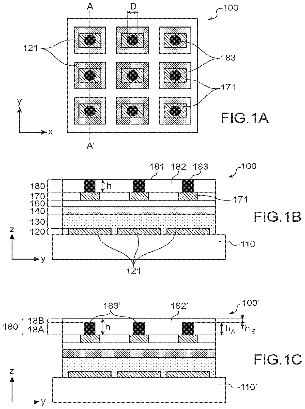
[0057]FIGS. 1A and 1B schematically show a thermal pattern sensor according to the invention;
[0058]FIG. 1C shows an alternative of the embodiment of FIGS. 1A and 1B;
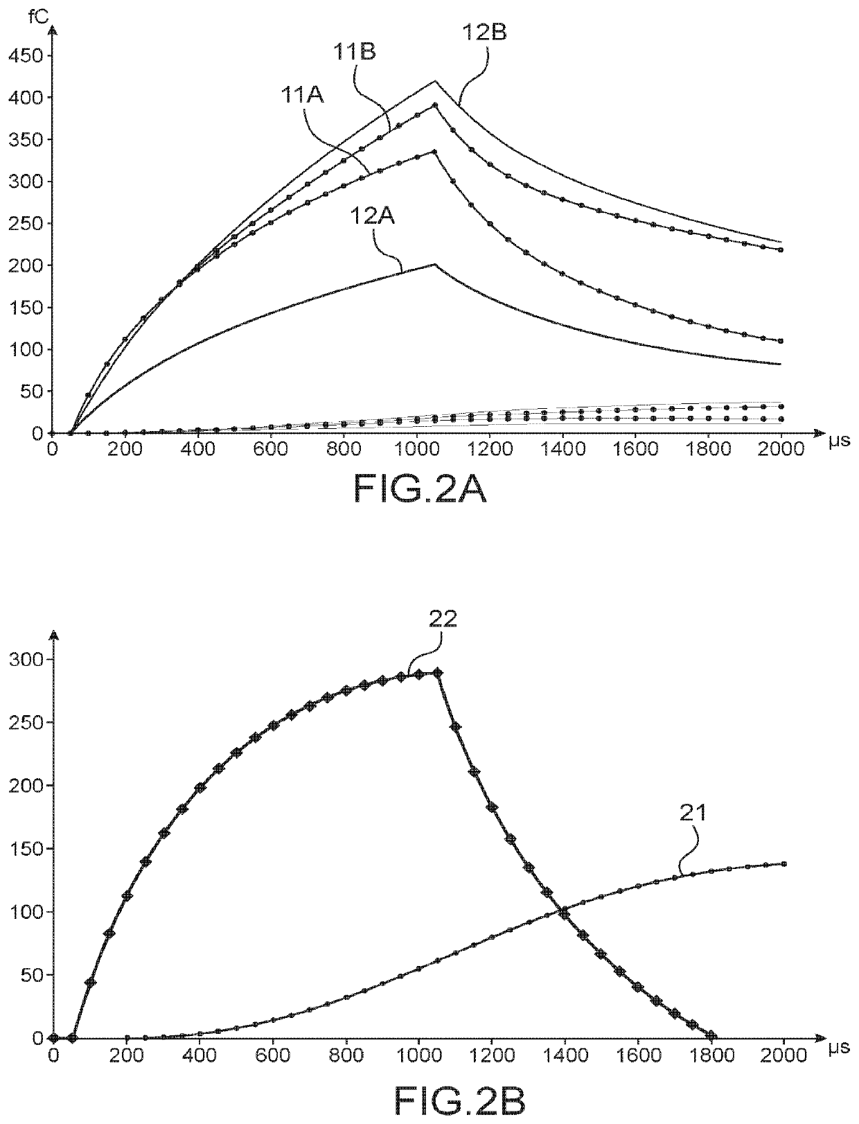
[0059]FIGS. 2A and 2B show a comparison of the thermal performances of a thermal pattern sensor according to the prior art or according to the invention;
second embodiment
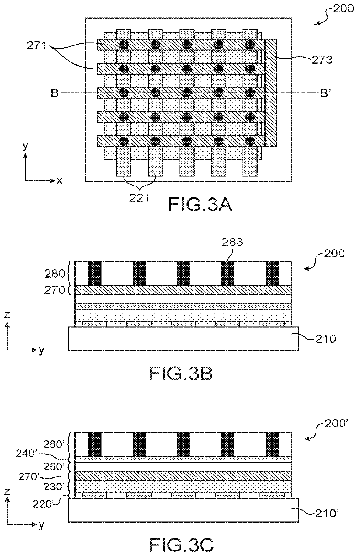
[0060]FIGS. 3A and 3B schematically show a thermal pattern sensor according to the invention;
[0061]FIG. 3C shows an alternative of the embodiment of FIGS. 3A and 3B; and
[0062]FIGS. 4 to 6 schematically show different embodiments of a method for producing a thermal pattern sensor according to the invention.
DETAILED DESCRIPTION OF SPECIFIC EMBODIMENTS
[0063]For greater clarity, the axes (Ox), (Oy) and / or (Oz) of an orthonormal reference system are shown in the figures. The figures, and in particular the thicknesses of each of the layers and / or stages and / or coating, are not drawn to scale.
[0064]FIGS. 1A and 1B schematically show a first embodiment of a thermal pattern sensor 100 according to the invention. FIG. 1A is a schematic top view, in a plane parallel to the plane (xOy). FIG. 1B is a cross-section view in a plane AA′ parallel to the plane (yOz).
[0065]The thermal pattern sensor 100 comprises, superimposed on a substrate 110, according to the axis (Oz) orthogonal to an upper or lo...
third embodiment
[0164]FIG. 6 shows a third embodiment, using a buffer 687, the recesses and protuberances of which are adapted to the desired positions of the pillars.
[0165]In this case, a solid layer 688 of a metallic ink is deposited on top of a stack 601 comprising the substrate 610, the pyroelectric capacitances and the heating elements. The buffer 687 having recesses 687A is then pressed at the desired locations of the pillars, so that the ink is preserved only in the locations of said recesses 687A.
[0166]Numerous alternatives using a buffer may be implemented, in which:[0167]droplets of a metallic ink are deposited, instead of a solid layer of metallic ink, before the buffer is pressed;[0168]the recesses of the buffer are filled with a metallic ink, then the assembly is applied to the stack as defined above, so that the ink in the recesses of the buffer adheres to the stack and detaches from the buffer when the latter is removed;[0169]a droplet of a metallic ink is deposited at the inlet of e...
PUM
| Property | Measurement | Unit |
|---|---|---|
| thickness | aaaaa | aaaaa |
| thickness | aaaaa | aaaaa |
| thickness | aaaaa | aaaaa |
Abstract
Description
Claims
Application Information
 - R&D
- Intellectual Property
- Life Sciences
- Materials
- Tech Scout
- Unparalleled Data Quality
- Higher Quality Content
- 60% Fewer Hallucinations
Browse by: Latest US Patents, China's latest patents, Technical Efficacy Thesaurus, Application Domain, Technology Topic, Popular Technical Reports.
© 2025 PatSnap. All rights reserved.Legal|Privacy policy|Modern Slavery Act Transparency Statement|Sitemap|About US| Contact US: help@patsnap.com


