Eureka AIR delivers breakthrough ideas for toughest innovation challenges, trusted by R&D personnel around the world.

Pyroelectric sensor with improved abrasion-resistance coating

a technology of pyroelectric sensors and coatings, applied in the field of pyroelectric sensortype thermal pattern sensor, can solve the problems of loss of resolution, inability to obtain satisfactory contrast, slow down the exchange of heat between pyroelectric capacitances,

Active Publication Date: 2020-04-23
COMMISSARIAT A LENERGIE ATOMIQUE ET AUX ENERGIES ALTERNATIVES
View PDF0 Cites 1 Cited by
  • Summary
  • Abstract
  • Description
  • Claims
  • Application Information

AI Technical Summary

Benefits of technology

The invention is about improving the thermal pattern sensor, which uses an anti-abrasion protection coating to protect its components from damage caused by abrasion. The coating has a unique structure that allows for quick thermal transfers in one direction and slow transfers in another direction, which helps to prevent heat from spreading too far in the coating. This results in a better thermal pattern image on the sensor. The invention also reduces the power consumption of the sensor by reducing the amount of heat supplied by the heating elements. Additionally, it overcomes the need for precise control over coating thickness, which allows for the use of a wider range of materials for the anti-abrasion protection layer.

Problems solved by technology

After several seconds, the temperature of the finger and the temperature of the contact surface get closer, and it is no longer possible to obtain a satisfactory contrast.
A disadvantage of such a resin layer, however, is that it slows down the exchanges of heat between the pyroelectric capacitances and an object to be imaged, due to the high thickness of the material to be passed through, and causes a loss in resolution due to the lateral conduction of heat to the adjacent pixels.
The pixel readout of the sensor is therefore slowed, which may present problems in particular for large-scale sensors with many pixels.
However, it remains technologically difficult and expensive to control the deposited thickness of DLC with as much precision, and the deposition temperatures are fairly incompatible with certain compounds constituting the pyroelectric sensor (in particular PVDF).

Method used


Image

  • Pyroelectric sensor with improved abrasion-resistance coating
  • Pyroelectric sensor with improved abrasion-resistance coating
  • Pyroelectric sensor with improved abrasion-resistance coating

Examples


first embodiment

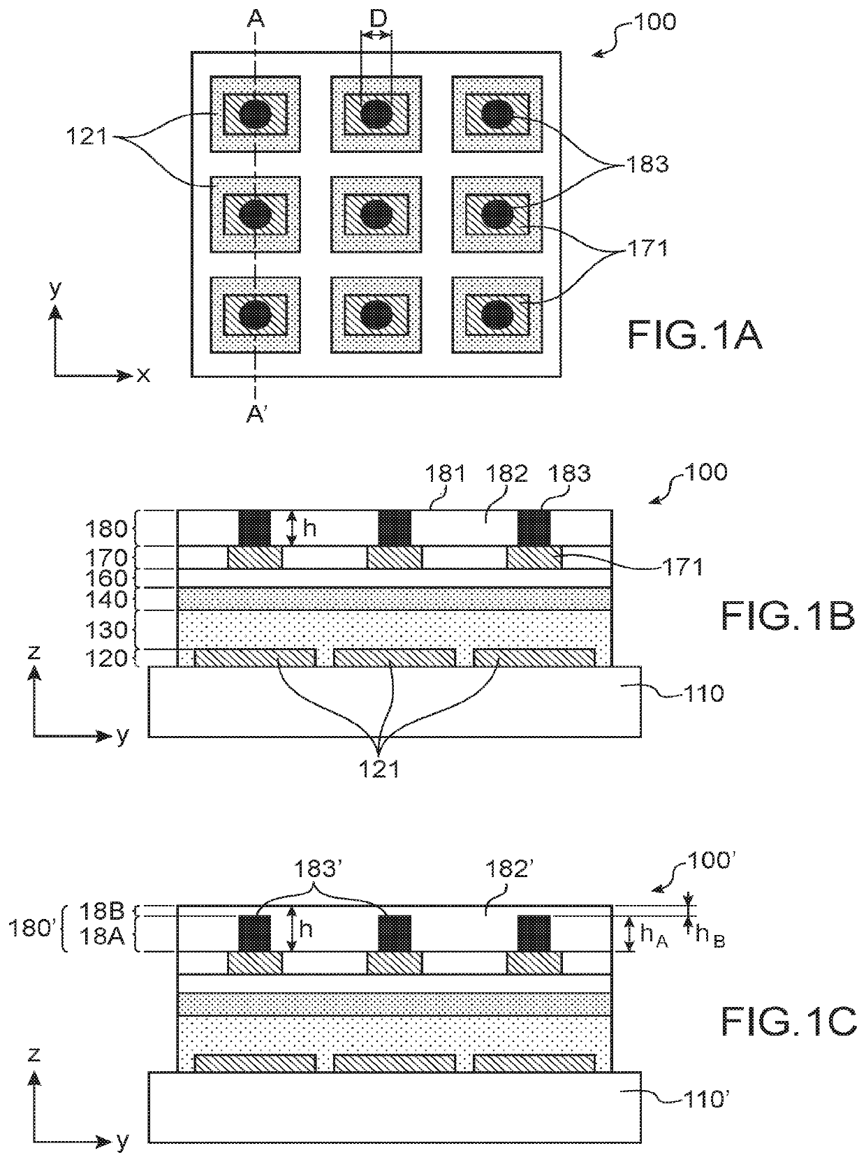
[0057]FIGS. 1A and 1B schematically show a thermal pattern sensor according to the invention;

[0058]FIG. 1C shows an alternative of the embodiment of FIGS. 1A and 1B;

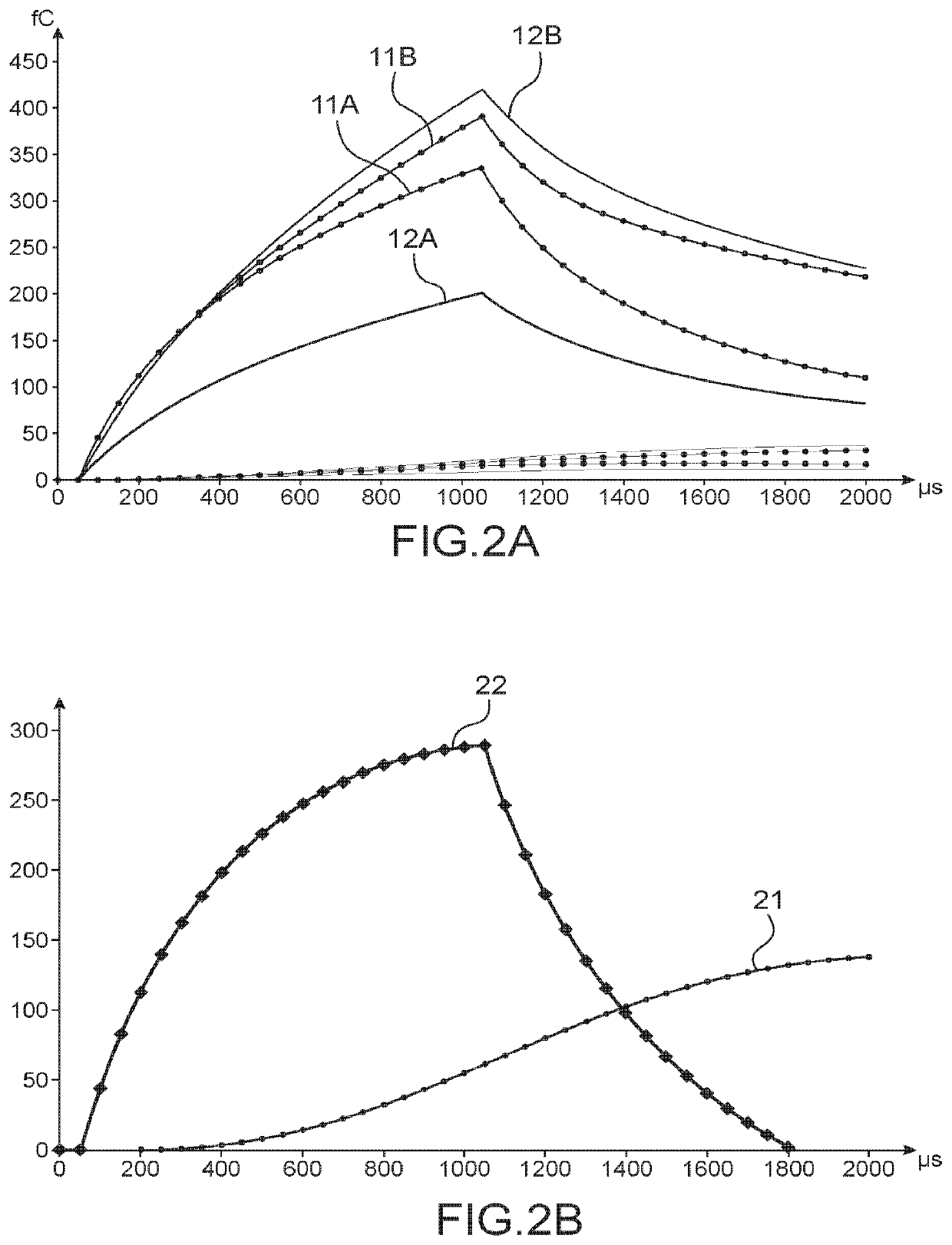
[0059]FIGS. 2A and 2B show a comparison of the thermal performances of a thermal pattern sensor according to the prior art or according to the invention;

second embodiment

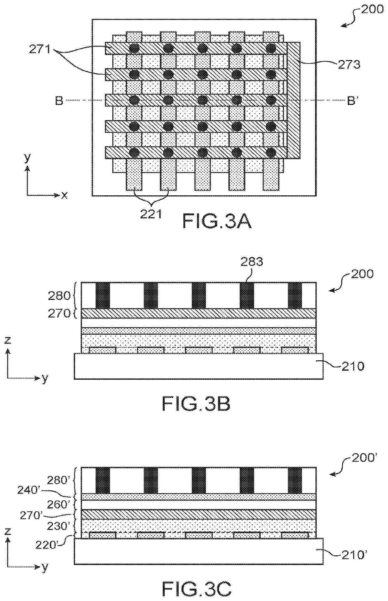
[0060]FIGS. 3A and 3B schematically show a thermal pattern sensor according to the invention;

[0061]FIG. 3C shows an alternative of the embodiment of FIGS. 3A and 3B; and

[0062]FIGS. 4 to 6 schematically show different embodiments of a method for producing a thermal pattern sensor according to the invention.

DETAILED DESCRIPTION OF SPECIFIC EMBODIMENTS

[0063]For greater clarity, the axes (Ox), (Oy) and / or (Oz) of an orthonormal reference system are shown in the figures. The figures, and in particular the thicknesses of each of the layers and / or stages and / or coating, are not drawn to scale.

[0064]FIGS. 1A and 1B schematically show a first embodiment of a thermal pattern sensor 100 according to the invention. FIG. 1A is a schematic top view, in a plane parallel to the plane (xOy). FIG. 1B is a cross-section view in a plane AA′ parallel to the plane (yOz).

[0065]The thermal pattern sensor 100 comprises, superimposed on a substrate 110, according to the axis (Oz) orthogonal to an upper or lo...

third embodiment

[0164]FIG. 6 shows a third embodiment, using a buffer 687, the recesses and protuberances of which are adapted to the desired positions of the pillars.

[0165]In this case, a solid layer 688 of a metallic ink is deposited on top of a stack 601 comprising the substrate 610, the pyroelectric capacitances and the heating elements. The buffer 687 having recesses 687A is then pressed at the desired locations of the pillars, so that the ink is preserved only in the locations of said recesses 687A.

[0166]Numerous alternatives using a buffer may be implemented, in which:[0167]droplets of a metallic ink are deposited, instead of a solid layer of metallic ink, before the buffer is pressed;[0168]the recesses of the buffer are filled with a metallic ink, then the assembly is applied to the stack as defined above, so that the ink in the recesses of the buffer adheres to the stack and detaches from the buffer when the latter is removed;[0169]a droplet of a metallic ink is deposited at the inlet of e...


PUM


Abstract

A thermal pattern sensor including a plurality of pixels arranged on a substrate. Each pixel has a pyroelectric capacitance formed by at least one pyroelectric material portion arranged between a lower electrode and an upper electrode. The sensor has an abrasion-resistance coating, located on the side opposite the substrate and including pillars embedded in an abrasion-resistance layer, the pillars having a thermal conductivity strictly higher than that of the abrasion-resistance layer. A high thickness of the anti-abrasion protection coating can be achieved with a high rate of thermal transfer through the latter.

Description

TECHNICAL FIELD[0001]The invention relates to a pyroelectric sensor-type thermal pattern sensor. Such a sensor forms, for example, a papillary print sensor, in particular a fingerprint sensor.PRIOR ART[0002]A pyroelectric sensor uses the properties of pyroelectricity of a material, i.e. its capacity to generate electric charges in response to a temperature variation.[0003]Such a sensor has pyroelectric capacitances, each forming a transducer for translating a time-dependent variation in temperature into an electric signal. Each pyroelectric capacitance has a portion made of a pyroelectric material, arranged between a lower electrode and an upper electrode. One of the electrodes is set to a constant potential, and forms a reference electrode. The other electrode, called the charge collection electrode, collects the pyroelectric charges generated by the pyroelectric material in response to a temperature variation. The charge collection electrode is connected to a readout circuit, for ...

Claims


Application Information

Patent Timeline
IPC IPC(8): G01J5/34G01J5/52G01J5/08G01J5/04
CPCG01J5/34G06K9/00053G01J5/048G01J5/52G01J5/0803G06V40/1329G06V40/1306
Inventor REVAUX, AMELIEBENWADIH, MOHAMMEDMAINGUET, JEAN-FRANCOIS
Owner COMMISSARIAT A LENERGIE ATOMIQUE ET AUX ENERGIES ALTERNATIVES
Why Eureka
Eureka Blog
Learn More