

Pseudorange calculation method, position calculation method, computer-readable recording medium, and position calculation device
- Summary
- Abstract
- Description
- Claims
- Application Information
AI Technical Summary
Benefits of technology
Problems solved by technology
Method used
Image

Examples
Embodiment Construction
[0039]Hereinafter, a preferred embodiment of the invention will be described with reference to the drawings. In the following description, a portable telephone unit is used as an exemplary electronic device having a positioning device, and the GPS (Global Positioning System) is used as a positioning system. However, embodiments to which the invention can apply are not limited to this.
1. Functional Configuration
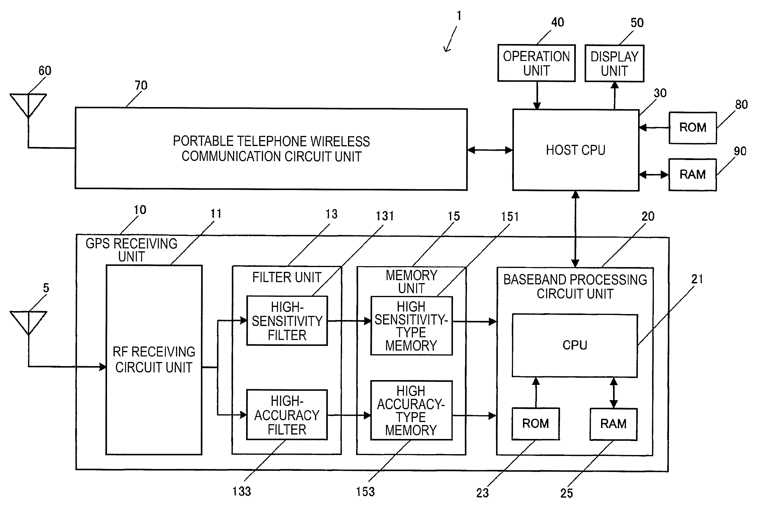
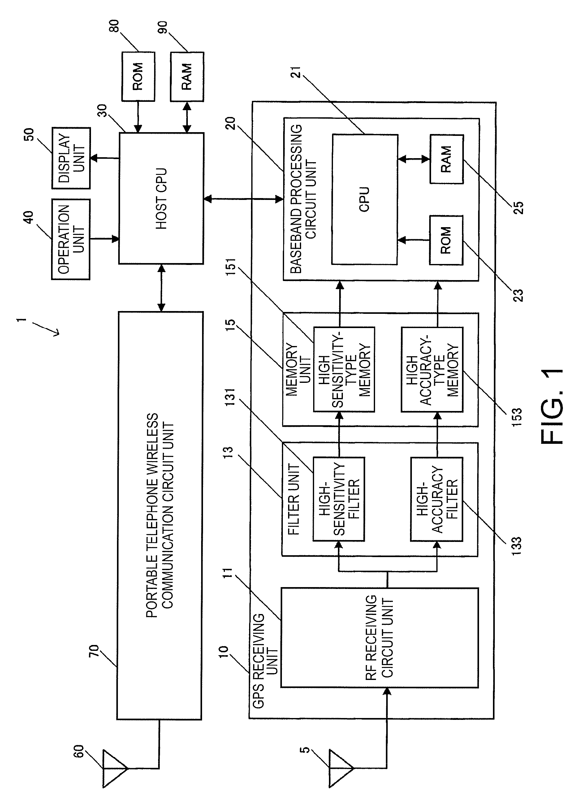
[0040]FIG. 1 is a block diagram showing the functional configuration of a portable telephone unit 1 according to this embodiment. The portable telephone unit 1 has a GPS antenna 5, a GPS receiving unit 10, a host CPU (central processing unit) 30, an operation unit 40, a display unit 50, a portable telephone antenna 60, a portable telephone wireless communication circuit unit 70, a ROM (read only memory) 80, and a RAM (random access memory) 90.
[0041]The GPS antenna 5 is an antenna which receives RF (radio frequency) signals including GPS satellite signals sent from GPS satellit...
PUM
 Abstract
Description
Claims
Application Information