Dual rotor vibration monitoring

a vibration monitoring and rotor technology, applied in the field of vibration, can solve the problems of turbine engine preventing unobstructed access, vibration monitoring and subsequent balancing, and corresponding vibration unbalance of the engine during operation over its operating speed,

Active Publication Date: 2009-10-22
GENRERAL ELECTRIC CO
View PDF14 Cites 28 Cited by
  • Summary
  • Abstract
  • Description
  • Claims
  • Application Information

AI Technical Summary

Benefits of technology

[0023]Since the two rotors have matched operating speed, the measured vibratory responses thereof will occur at the same frequency and it is therefore impossible to distinguish the separate vibratory responses of the two rotors from each other using the conventional frequency analysis procedure described above.

Problems solved by technology

Accordingly, the center of gravity of each rotary stage in the engine may be slightly offset or eccentric from the centerline axis which will then result in corresponding vibratory unbalance of the engine during operation over its operating speeds.
However, in practice the inherent complexity of the modem gas turbine engine prevents unobstructed access to most of the rotating stages, and balance corrections are typically applied at an accessible stage such as the fan.
However, a new type of turbofan engine creates a special problem in vibration monitoring and subsequent balancing.

Method used


Image

  • Dual rotor vibration monitoring
  • Dual rotor vibration monitoring
  • Dual rotor vibration monitoring

Examples


Embodiment Construction

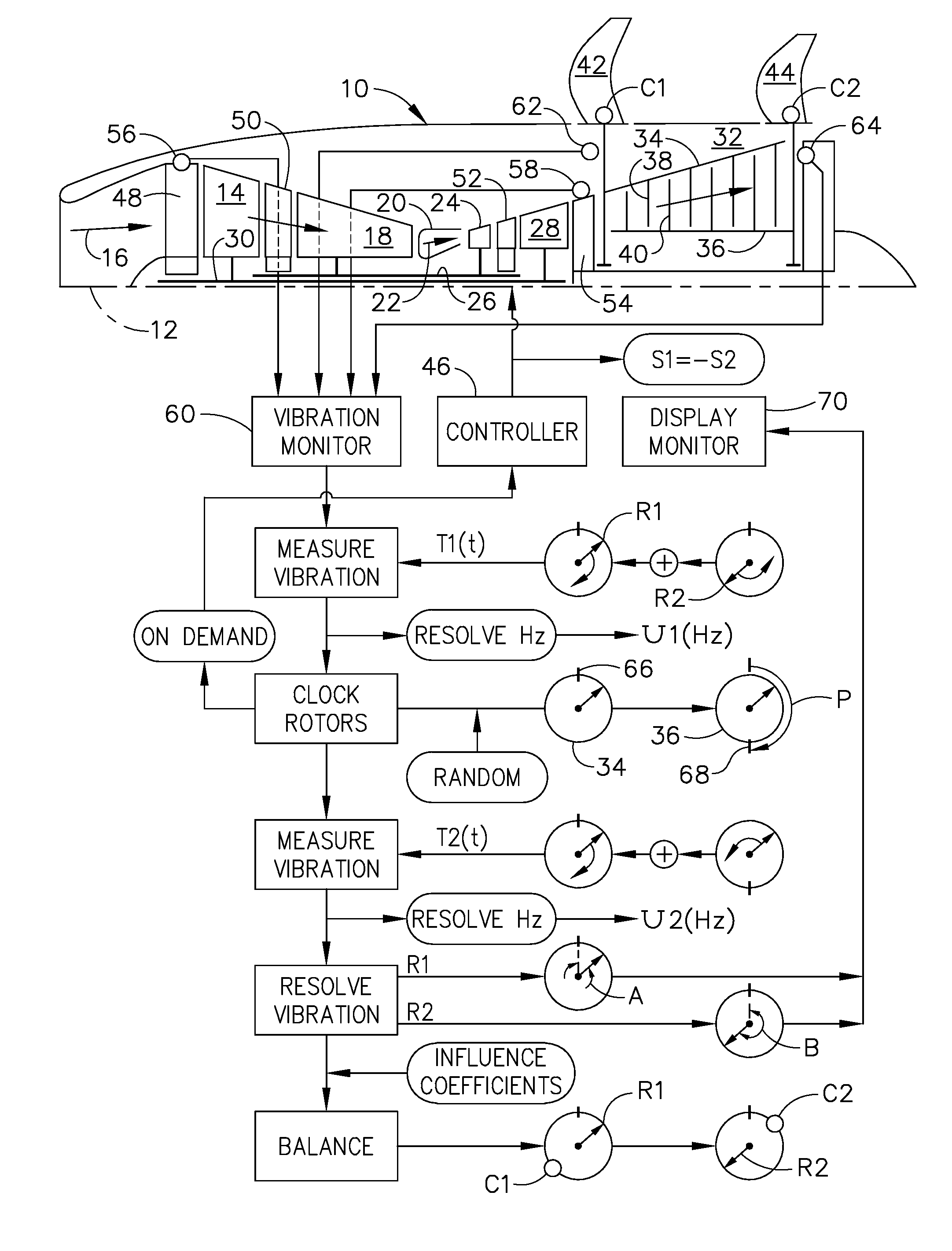
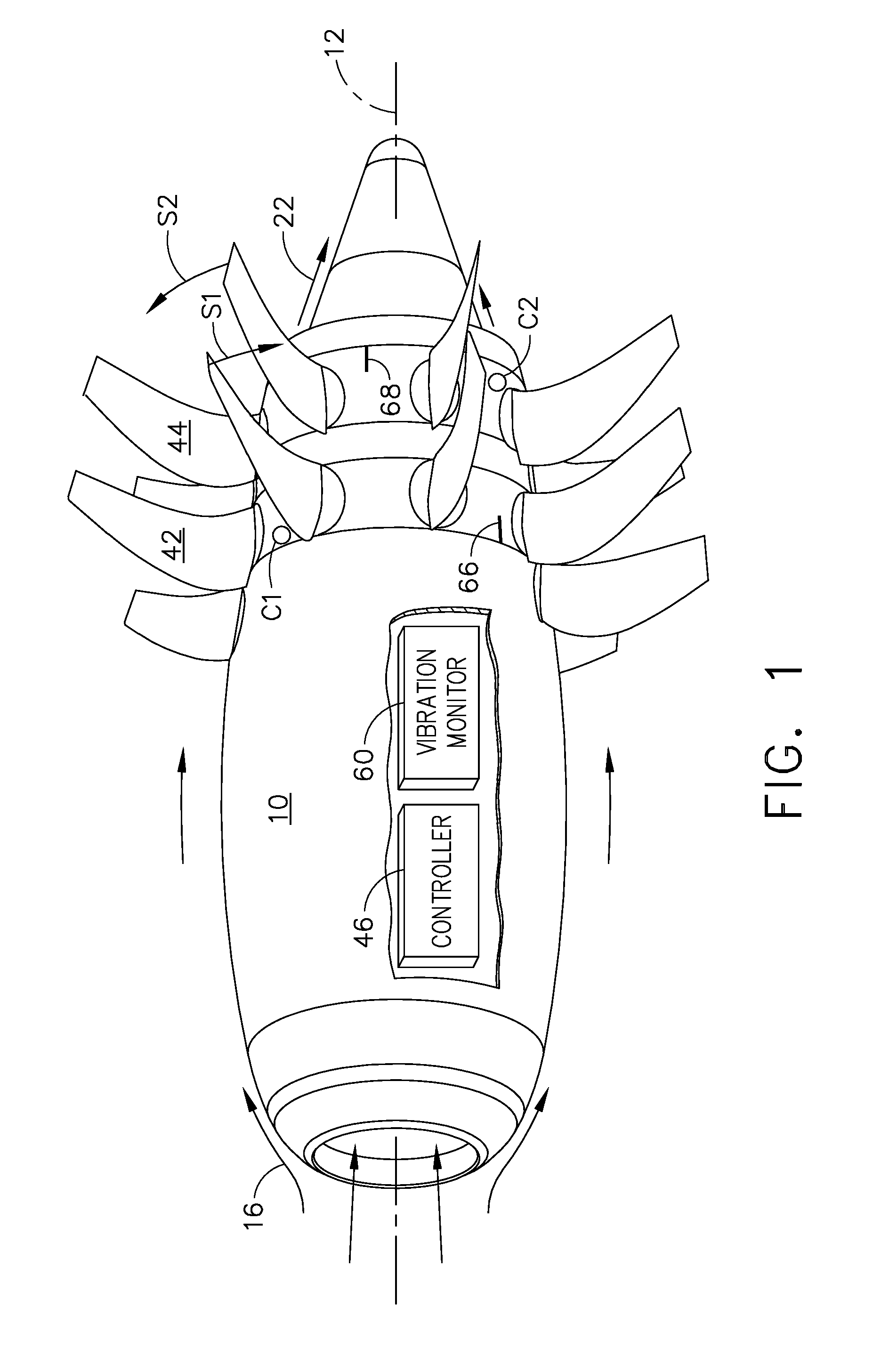
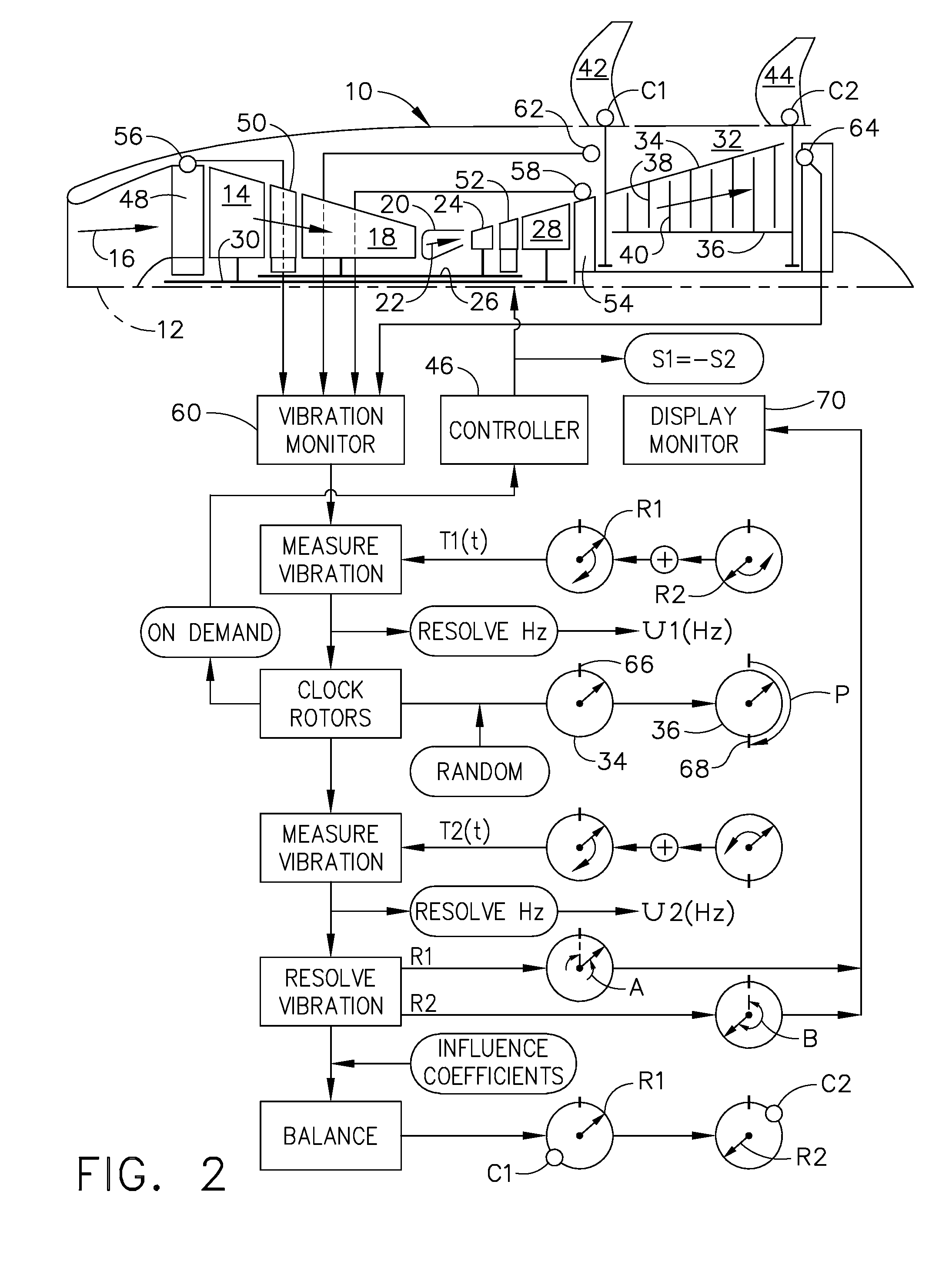
[0029]Illustrated in FIG. 1 is a unducted fan (UDF) turbofan aircraft engine 10 which is axisymmetrical about a longitudinal or axial centerline axis 12. The engine is shown schematically in FIG. 2 and includes a low pressure fan or booster compressor 14 which first receives ambient air 16 for pressurization thereof.

[0030]A multistage, high pressure axial compressor 18 follows the fan 14 for further pressurizing the air 16 which is then mixed with fuel inside an annular combustor 20 for generating hot combustion gases 22.

[0031]A high pressure turbine (HPT) 24 first receives the hot combustion gases from the combustor and powers the compressor 18 through a first drive shaft 26.

[0032]An intermediate pressure turbine (IPT) 28 follows the HPT 24 and drives the fan 14 through a second drive shaft 30 disposed concentrically inside the first drive shaft 26.

[0033]A low pressure turbine (LPT) 32 follows the IPT 28 and receives the combustion gases therefrom. The LPT includes a first or outer...


PUM


Abstract

Vibration is monitored in a dual rotor engine. A first total vibration of the engine is measured during operation. Relative phase of the two rotors is then clocked, and a second total vibration of the engine is then measured during operation. First and second total unbalances are then resolved at a common response frequency from the measured total vibrations. First and second rotor unbalances are then resolved for the corresponding rotors from the first and second total unbalances. In a further method, corresponding corrective balance weights may be determined for offsetting the resolved rotor unbalances.

Description

BACKGROUND OF THE INVENTION[0001]The present invention relates generally to gas turbine engines, and, more specifically, to vibration therein.[0002]In a gas turbine engine, air is pressurized in a compressor and mixed with fuel in a combustor for generating hot combustion gases discharged into a high pressure turbine (HPT) that powers the compressor. And, the gases are then discharged through a low pressure turbine (LPT) that typically powers a fan in a turbofan aircraft engine application.[0003]The HPT rotor blades power the corresponding rotor blades of the compressor through one drive shaft, and the LPT rotor blades power the fan blades through another drive shaft. The drive shafts and associated rotor blades are suitably mounted in bearings supported in corresponding frames in the engine.[0004]The HPT and its drive shaft operate at substantially high rotary speed during operation, and the LPT and its drive shaft operate at a relatively low rotary speed for powering the fan blade...

Claims


Application Information

Patent Timeline
Patent Type & Authority Applications(United States)
IPC IPC(8): F01D25/04G01M1/22
CPCF01D21/003F05D2260/96F01D25/04G01H1/006
Inventor MOLLMANN, DANIEL EDWARD
Owner GENRERAL ELECTRIC CO
Why Eureka
Try Eureka