Capacitive sensor
a capacitive sensor and sensor technology, applied in the direction of speed/acceleration/shock measurement, resistance/reactance/impedence, instruments, etc., can solve the problems of generating deficit or sticking of a member, prone to increase and reducing stress generated in the beam. , to achieve the effect of enhancing detection sensitivity, avoiding the movement of a movable electrode, and reducing the size of the devi
- Summary
- Abstract
- Description
- Claims
- Application Information
AI Technical Summary
Benefits of technology
Problems solved by technology
Method used
Image
Examples
first embodiment
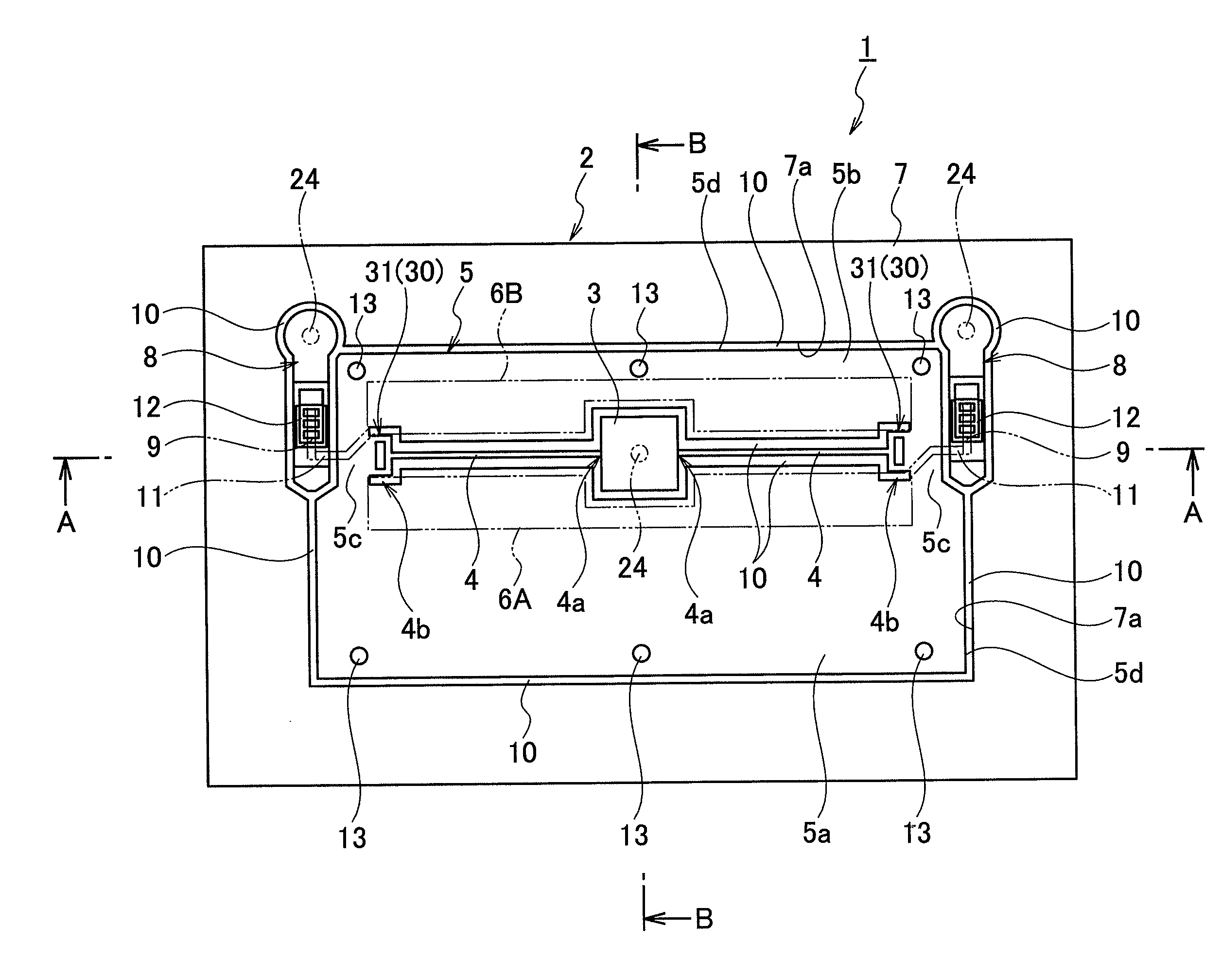
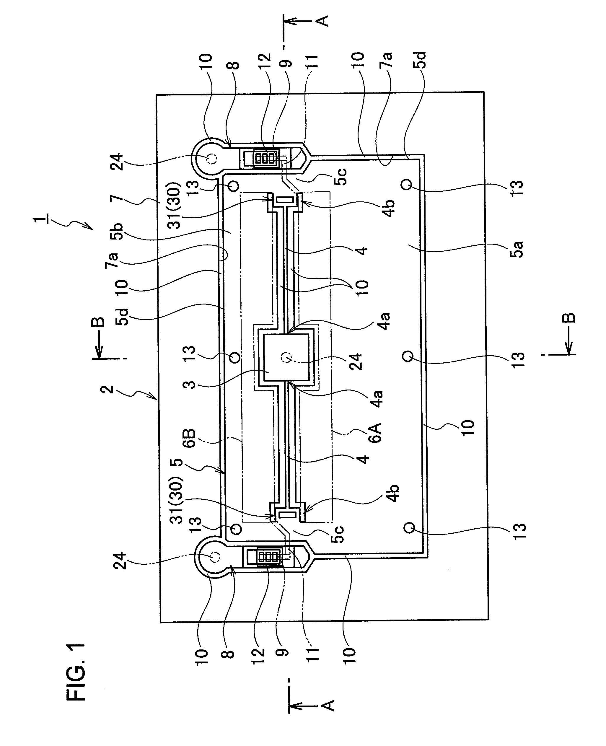
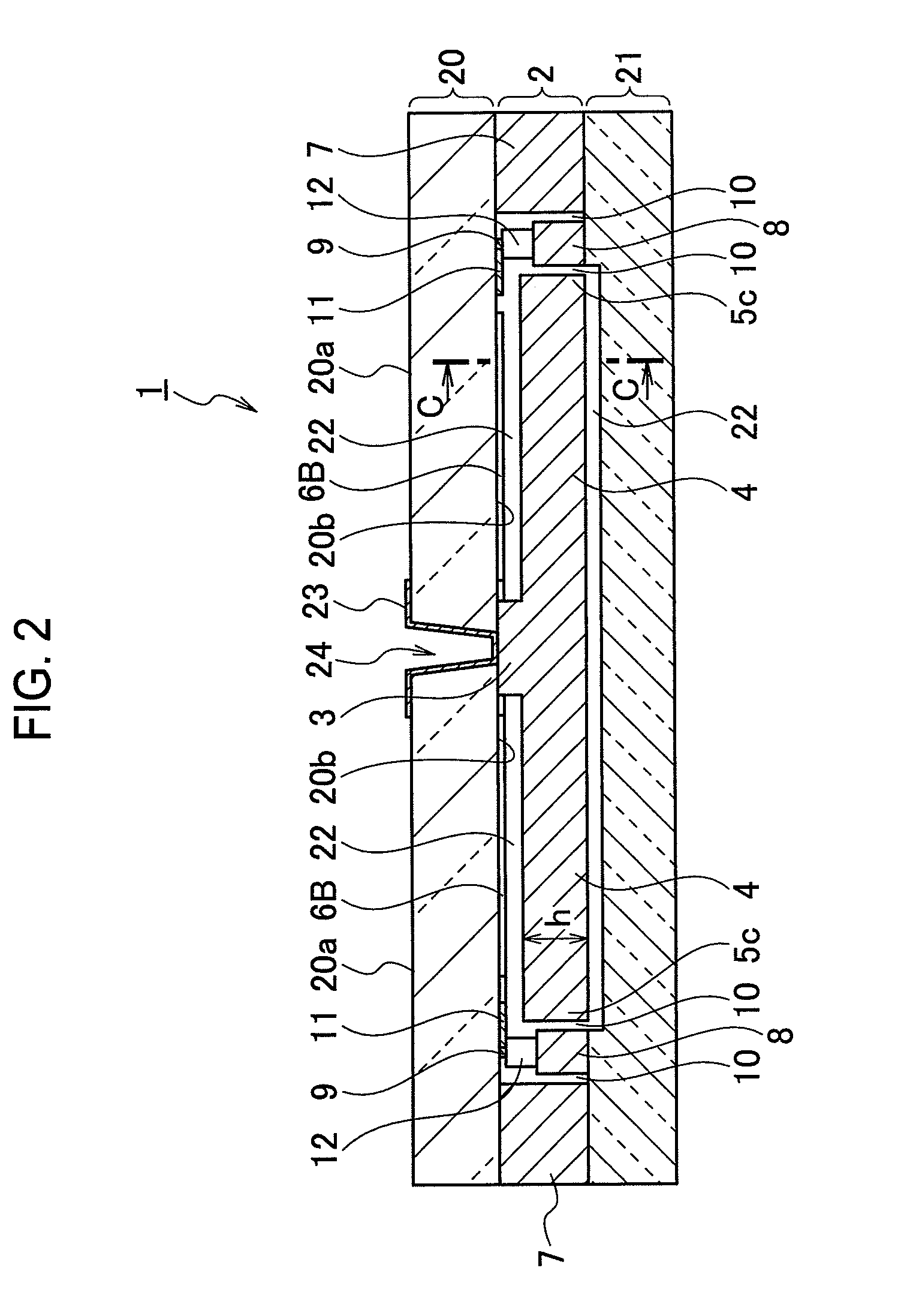
[0036]As shown in FIG. 2, a capacitive sensor 1 (hereinafter, simply sensor 1) as a first embodiment of the present invention has a semiconductor layer 2 obtained by processing a semiconductor substrate, and insulation layers 20 and 21 such as glass substrates are bonded on both front and back sides by anodic bonding. Relatively shallow recesses 22 are formed in bonded surfaces between the semiconductor layer 2 and the insulation layers 20 and 21, insulation properties of the semiconductor layer 2 and moving easiness of the movable electrode 5 are secured. In the present embodiment, the bonded surface between the semiconductor layer 2 and the insulation layer 20 is provided with the recess 22 on the side of the semiconductor layer 2, and the bonded surface between the semiconductor layer 2 and the semiconductor layer 2 is provided with the recess 22 on the side of the insulation layer 21.
[0037]A conductive layer 23 is formed on a surface 20a of the insulation layer 20, and the condu...
second embodiment
[0067]The sensor 1 as a second embodiment of the present invention is different from the structure of the sensor 1 as the first embodiment in that ends of the beam portions 4 and 4 in the longitudinal direction are not provided with the stress moderating units 30 as shown in FIG. 9. In the second embodiment, as shown in FIG. 10(a), the semiconductor layer 2 is bonded to the insulation layer 20, and before the gap 10 is formed, the recess 22 is formed by various etching processes such as wet etching and dry etching. After cutting the semiconductor layer 2 away by the etching, the insulation layer 20 which is a glass substrate is bounded as shown in FIG. 10(b), vertical etching working is carried out, thereby forming the gap 10 as shown in FIG. 10(c). The stopper 13 is formed of oxide film or aluminum alloy after the recess 22 is formed by etching process.
[0068]By etching the semiconductor layer 2 which is the single crystal silicon substrate in this manner, the recess 22 is formed pr...
third embodiment
[0092]Next, a structure of the sensor 1 shown as a third embodiment of the present invention will be explained with reference to FIGS. 17 and 18. The sensor 1 shown as the third embodiment is identical to the sensor 1 shown as the second embodiment that detects a physical value in the vertical direction which is the thickness direction of the semiconductor layer 2, except that the sensor 1 shown as the third embodiment can detect a physical value in the horizontal direction which is a plane direction of the semiconductor layer 2.
[0093]FIG. 17 is a plan view showing the semiconductor layer 2 of the sensor 1. As shown in FIG. 17, the semiconductor layer 2 includes a vertical direction detecting unit 50A that detects a physical value in the vertical direction by forming a gap 10 in the semiconductor substrate by a known process, a horizontal direction detecting unit 50B that detects a physical value in the horizontal direction, and a frame portion 7 surrounding these units. Since the v...
PUM
 Abstract
Description
Claims
Application Information
 - R&D
- Intellectual Property
- Life Sciences
- Materials
- Tech Scout
- Unparalleled Data Quality
- Higher Quality Content
- 60% Fewer Hallucinations
Browse by: Latest US Patents, China's latest patents, Technical Efficacy Thesaurus, Application Domain, Technology Topic, Popular Technical Reports.
© 2025 PatSnap. All rights reserved.Legal|Privacy policy|Modern Slavery Act Transparency Statement|Sitemap|About US| Contact US: help@patsnap.com


