Bumper system for vehicle

a bumper system and vehicle technology, applied in the direction of bumpers, vehicle components, vehicular safety arrangments, etc., can solve the problems of high rigidity, high strength to be deteriorated, not yet put to practical use, etc., to simplify the joining, increase the number of choices for joining, and facilitate the manufacturing of impact buffer members

Inactive Publication Date: 2009-10-29
KOBE STEEL LTD
View PDF4 Cites 20 Cited by
  • Summary
  • Abstract
  • Description
  • Claims
  • Application Information

AI Technical Summary

Benefits of technology

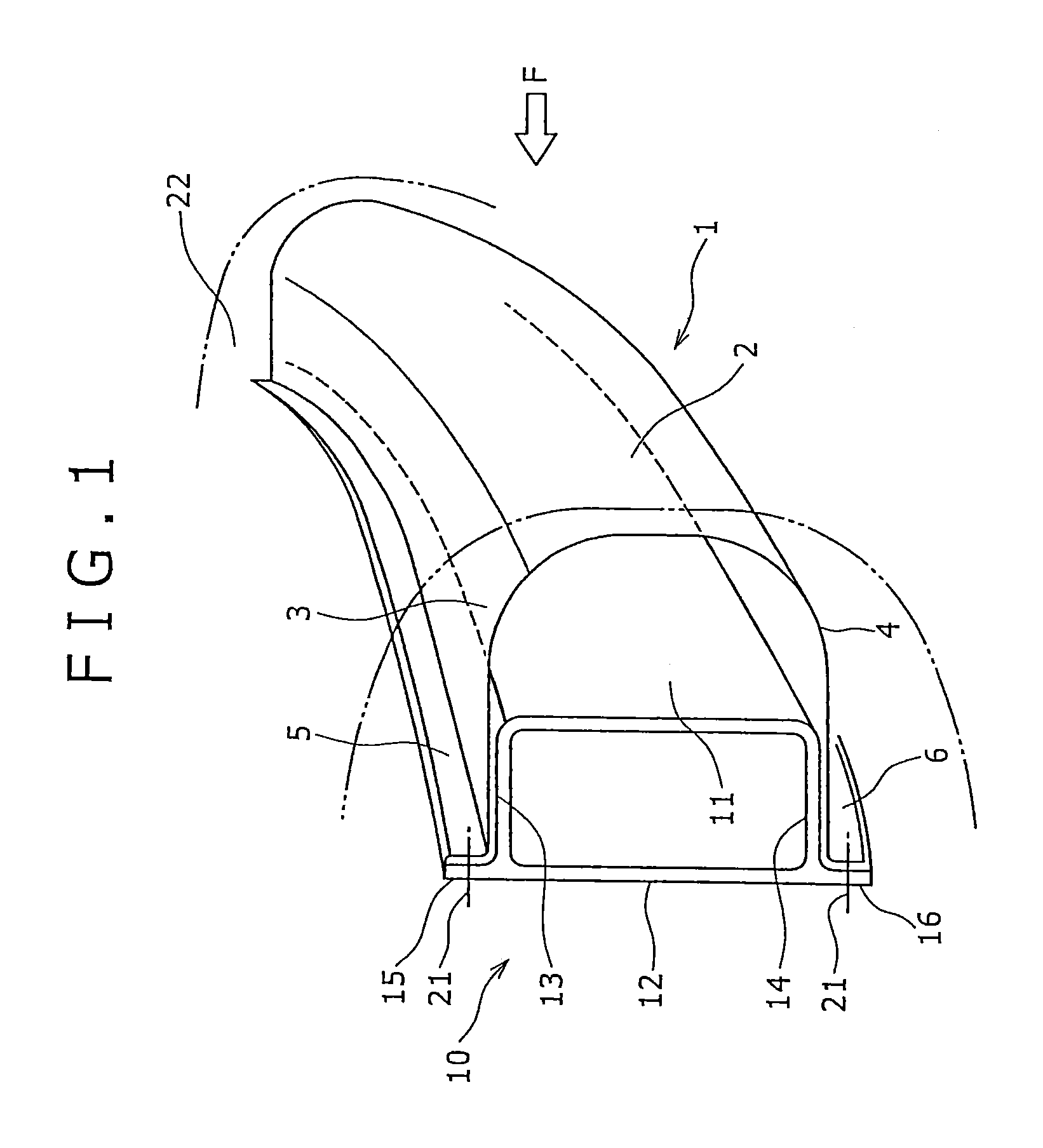
[0032]With this arrangement, the joining of the impact buffer member and the bumper beam becomes the joining of flanges to each other, therefore the generally used mechanical joining means such as bolts or rivets and the generally used weld joining means such as spot welding become applicable to increase the number of choices for joining and to simplify the joining itself. With this configuration, the supporting and the joining force of the impact buffer member against the bumper beam is controllable over the longitudinal direction of the impact buffer member. In other words, it is possible to secure the energy absorption amount required for the pedestrian protection and to secure the displacement of the impact buffer member in the longitudinal direction of the vehicle (the direction of the thickness of the section) and to control the reaction force and the acceleration generated at the time of the collision.
[0033]Moreover, all of the colliding wall, side walls and joint flanges of the impact buffer member are integrally formed of a comparatively thin metallic material such as a sheet of aluminum alloy plate. Thereby, manufacturing of the impact buffer member becomes easy compared with joining separate members. In addition, there will be no breakage of joining parts by the impact at the time of the vehicle collision, to allow an improved energy absorbing function at the time of the collision.
[0034]Consequently, the bumper system for a vehicle of the present invention can lower the generated load, the acceleration, or the like at the time of the collision and can secure the characteristics required for pedestrian protection even in the case that the width of the impact buffer member is comparatively narrowed (thinning).

Problems solved by technology

On the contrary, in the bumper systems designed with lowered strength and rigidity in order to protect pedestrians, the functions of reducing the impact load and absorbing the impact energy at the time of collision with the pedestrian's body causes high rigidity and high strength to be deteriorated.
In this regard, although a variety of ideas such as arranging an impact absorbing device or an air bag in front of the bumper beam (bumper reinforcement) are conventionally proposed, they are not yet put to practical use.
However, in designing a vehicle body, there is a limit in the thickness of the absorber arranged, and there actually is a limit in the pedestrian protecting performance (impact energy absorbing function) as well.
Also, in its production, the material and the thickness of resin are restricted and the problem of inferior recycling property compared to the cushioning material made of a metal is involved.
Accordingly, it may possibly happen that the collision position of a pedestrian largely shifts from the position where the energy absorbing member is installed.
In the cushioning member utilizing the collapse to the direction of the thickness of the section, if the line of action of the compressing force is shifted, the energy absorbing performance becomes liable to be deteriorated.
From this viewpoint, in such a cushioning member, the energy absorption amount required for protection of a pedestrian is hard to be secured.

Method used


Image

  • Bumper system for vehicle
  • Bumper system for vehicle
  • Bumper system for vehicle

Examples


example

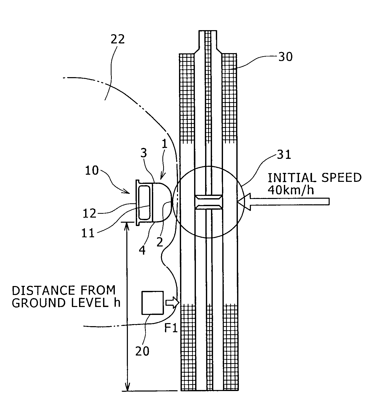
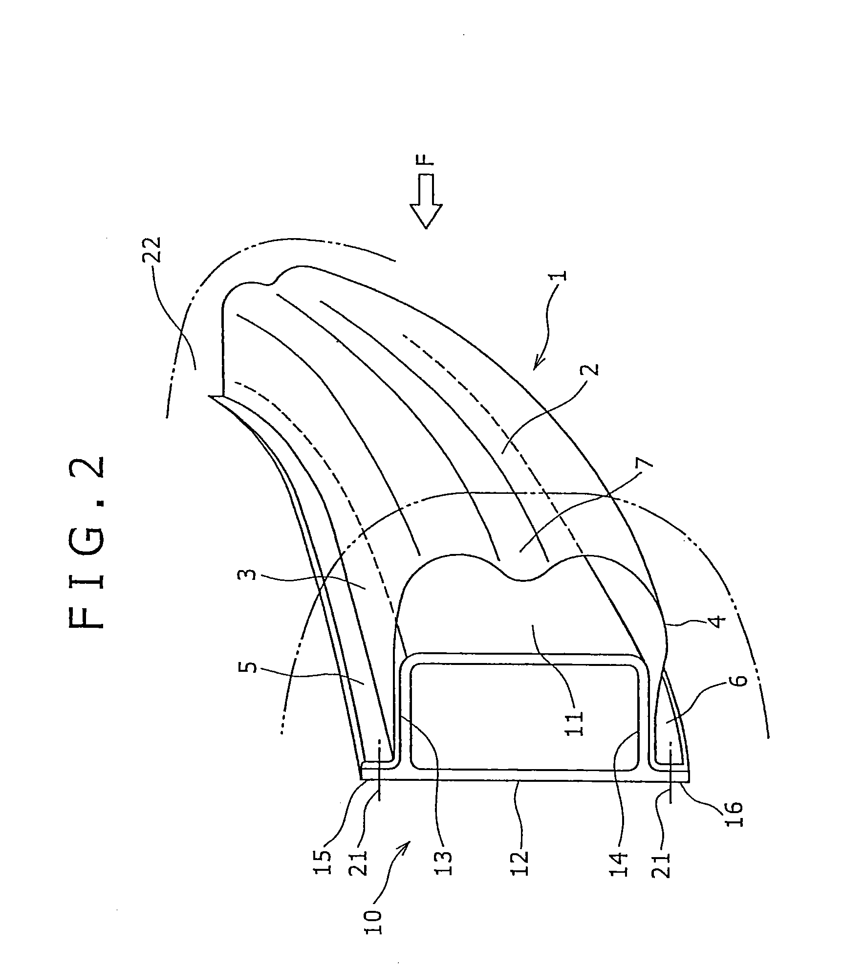
[0084]The bumper systems of the present invention described above as illustrated in FIGS. 1, 2 were analytically modeled and acceleration-displacement relations by a static collapsing analysis at the time of loading assuming the collision with the pedestrian were obtained with an analysis using the generalized finite element analysis software ABAQUS. In the analytic model of the example of the invention, an absorber was not provided. However, as an embodiment of usage according to the present invention, an absorber composed of PP foam or the like may be arranged (an absorber may be combined with) in the front side of the impact buffer member 1. Also, as is illustrated in FIG. 3, it may be combined with a separate means 20 or the like arranged under the bumper system for kicking up the lower part of the leg in the reverse direction of the direction of the collision by the force F1 shown in the arrow at the time of the collision and preventing excessive bending (big bending angle) of ...


PUM


Abstract

The bumper system for a vehicle body includes a vehicle body bumper beam of a hollow construction with an impact buffer member arranged in the front side. The impact buffer member is provided with a collision wall part, side wall parts and joint flanges and is integrally formed by a metallic material, the collision wall part and the side wall parts forming a sectional shape of approximately U-shape which embraces the bumper beam. The joint flanges are joined with the flanges protruding from the rear wall of the bumper beam and support the impact buffer member from the rear wall side of the bumper beam.

Description

BACKGROUND OF THE INVENTION[0001]1. Field of the Invention[0002]The present invention relates to a bumper system for a vehicle excellent in load energy absorbing performance at the time of a vehicle collision, particularly excellent in characteristics mitigating the impact applied to a human body and reducing the damage to a pedestrian at the time of the collision with the pedestrian.[0003]2. Description of the Related Art[0004]On the vehicle body of automobiles and the like, a bumper system reducing the impact load by deforming in the direction of the collision and absorbing the impact energy for ensuring the safety of an occupant and protecting a collided pedestrian's body at the time of the vehicle collision is known.[0005]A representative example of the bumper system is the one constituted of a bumper beam of iron and steel or of an aluminum alloy mounted at the front face of bumper stays, a cushioning material of foamed resin arranged in front of it, and further in front of whi...

Claims


Application Information

Patent Timeline
Patent Type & Authority Applications(United States)
IPC IPC(8): B60R19/26
CPCB60R2019/182B60R19/18
Inventor HASHIMURA, TORU
Owner KOBE STEEL LTD
Why Eureka
Try Eureka