
High-pressure discharge lamp and lighting equipment

a high-pressure discharge and lamp technology, applied in the direction of gas discharge lamp details, electric discharge tubes, vacuum tube vessels/containers/shields, etc., can solve the problems of insufficient color rendering and visibility, inability to use for illumination that requires a large quantity of light, and insufficient ultraviolet rays-cutting layer to minimize and inhibit the color change of paper and fabrics. , to achieve the effect of suppressing the low brightness, excellent color visibility and color rendering

Inactive Publication Date: 2009-10-29
TOSHIBA LIGHTING & TECH CORP
View PDF16 Cites 4 Cited by
  • Summary
  • Abstract
  • Description
  • Claims
  • Application Information

AI Technical Summary

Benefits of technology

[0016]An object of the present invention is to provide a high-pressure discharge lamp and lighting equipment, which are excellent in visibility of color and in color rendering and are capable of adjusting the color temperature to 3200-3700K while suppressing the lowing of brightness.

Problems solved by technology

Further, since the wavelength dependency of insect attractiveness and of color changes of paper and fabrics is as large as a wavelength of nearly 500 nm in the visible-light region, the effects of this ultraviolet rays-cutting layer to minimize and inhibit the color change of paper and fabrics and the attraction of insects cannot be said as being sufficient.
However, this lamp is insufficient in color rendering and in visibility so that it cannot be used for the illumination that requires a large quantity of light.
Further, in the case of Document 5, when the lamps were experimentally manufactured based on the specification described therein and the characteristics of the lamps were measured, it was found impossible, in some cases, to obtain desired emission characteristics, depending on the kinds of lamps which differ in electric power from the rated power described in the examples of Document 5.
Because of this, it may become impossible, depending on the kind of rare earth metal halide, to obtain the desired characteristics described therein.
However, the luminescent color of the lamp was caused to turn into green color substantially and the average evaluation number of color rendering was decreased to 75 or less, thereby making the lamp unsuitable for use in a store or for outdoor illumination.

Method used


Image

  • High-pressure discharge lamp and lighting equipment
  • High-pressure discharge lamp and lighting equipment
  • High-pressure discharge lamp and lighting equipment

Examples


first embodiment

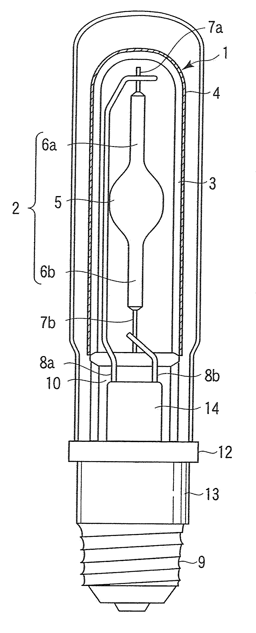
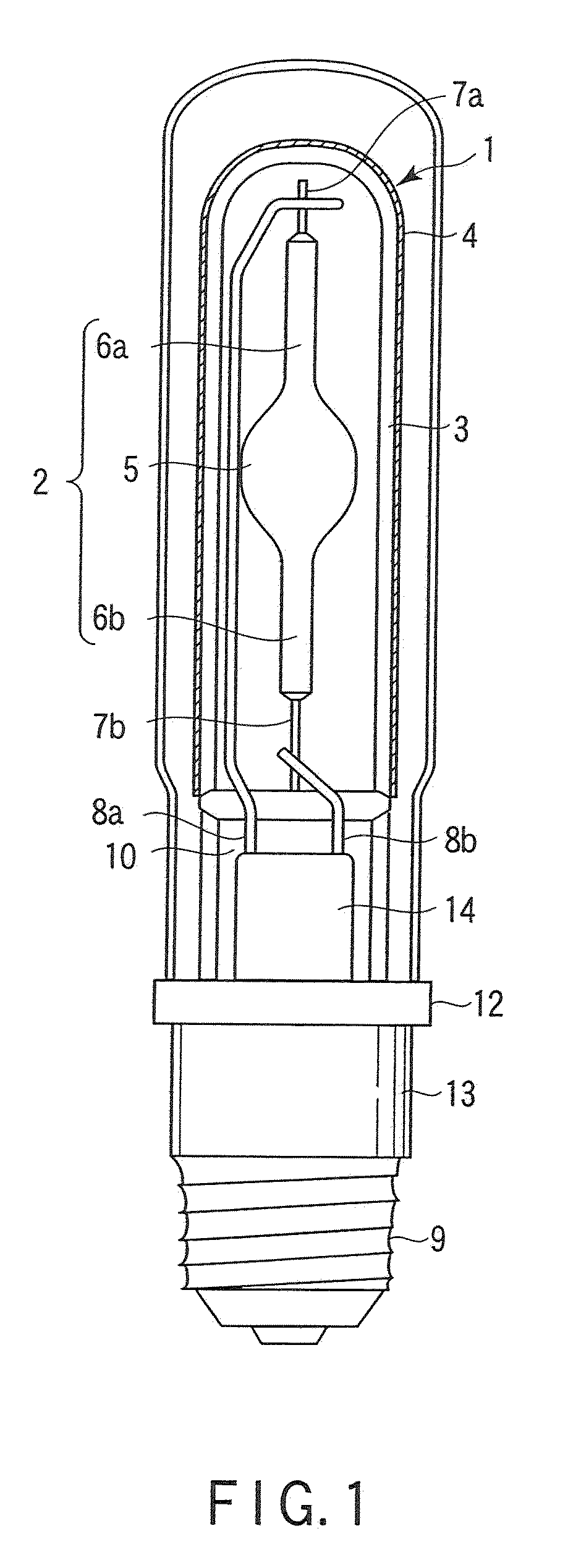
[0042]FIG. 1 shows one example of the high-pressure discharge lamp according to the first embodiment of the present invention.

[0043]Reference number 1 in this FIG. 1 denotes a metal halide lamp representing the high-pressure discharge lamp and equipped with a ceramic luminous tube 2. An inner tube 3 acting as a transparent protective tube is disposed so as to surround the luminous tube 2, thereby protecting the luminous tube 2. An Edison type base 9 connected electrically with the luminous tube 2 and hence acting as a feeding means is attached to the inner tube 3. A light-cutting layer 4 for cutting light of predetermined wavelength is deposited on the outer surface of the inner tube 3. This light-cutting layer 4 is, for example, constructed such that it comprises, as main components, particles of indium-doped zinc oxide and particles of metal oxide which are capable of absorbing light having a wavelength no greater than 600 nm and enabling light having a wavelength of greater than ...

second embodiment

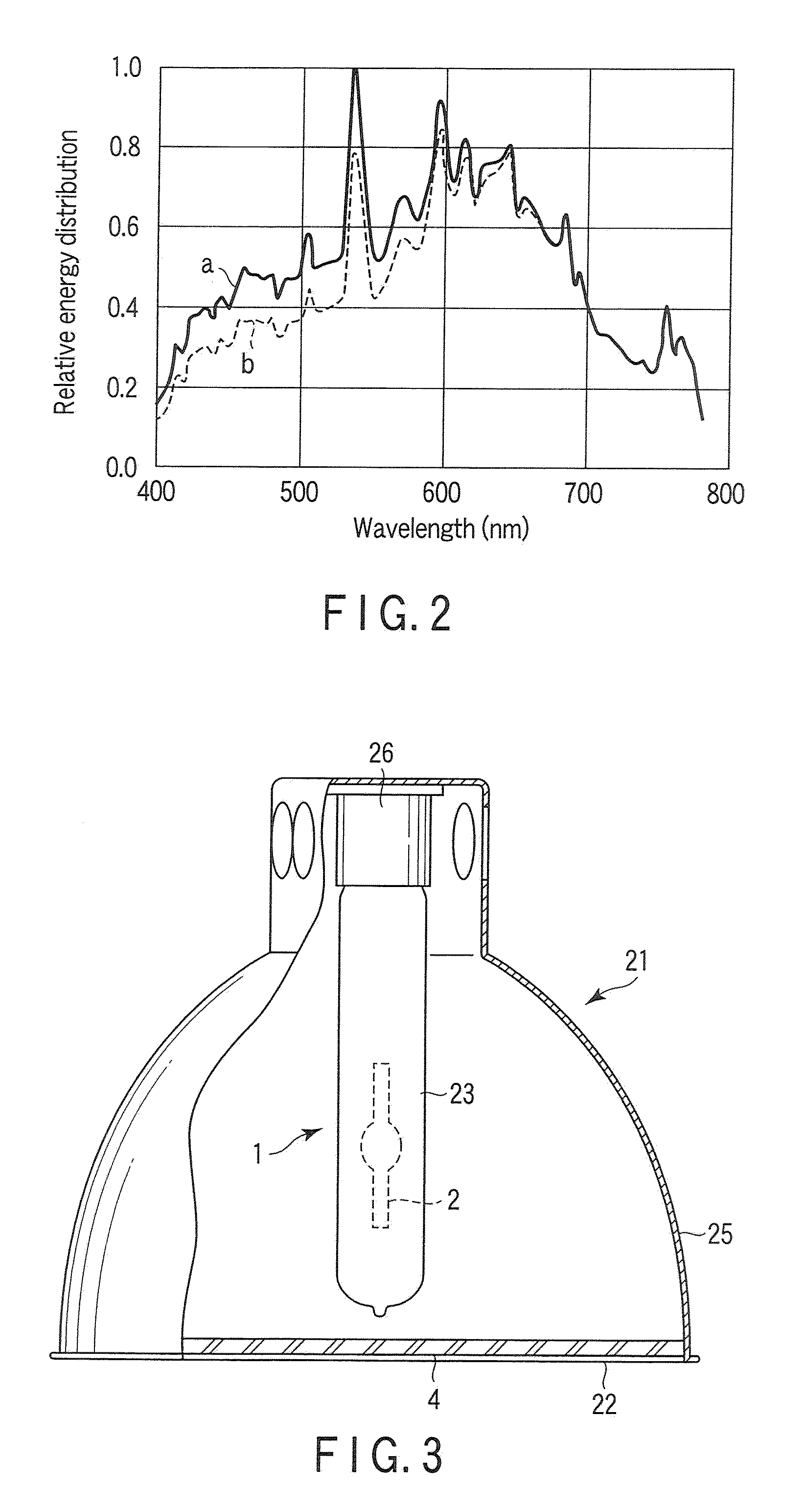
[0052]FIG. 3 is a schematic sectional view showing the lighting equipment according to the second embodiment of the present invention.

[0053]Reference number 21 in this FIG. 3 denotes lighting equipment wherein the aforementioned light-cutting layer 4 having almost the same optical characteristics as the first embodiment is attached to the front cover glass 22 of the lighting equipment. The high-pressure discharge lamp 1 is a metal halide lamp wherein a light-cutting layer is not mounted on the outer lube bulb 23. This high-pressure discharge lamp 1 is used by accommodating it in the lighting equipment 21. This lighting equipment 21 is equipped with a reflector 25 having an opened bottom surface and a socket 26 is attached to the ceiling of this reflector 25. This high-pressure discharge lamp 1 is secured to the lighting equipment 21 through engagement between the base thereof and the socket 26. The light-cutting layer 4 is formed on the cover glass 22 in the same manner as described...

third embodiment

[0055]FIGS. 4A and 4B show one example of the high-pressure discharge lamp according to the third embodiment of the present invention. Specifically, FIG. 4A shows a general of the high-pressure discharge lamp and FIG. 4B shows a plan view of an elastic retention member constituting one component of the high-pressure discharge lamp of FIG. 4A.

[0056]Reference number 31 in this FIG. 4A denotes a metal halide lamp representing a high-pressure discharge lamp and equipped with a ceramic luminous tube 32. An inner tube 33 acting as a transparent protective tube is disposed so as to surround the luminous tube 32, thereby protecting the luminous tube 32. An Edison type base 34 connected electrically with the luminous tube 32 and hence acting as a feeding means is attached to the inner tube 33. A translucent outer tube 35 is mounted around the inner tube 33. A lower end of the outer tube 35 is fixed to a ceramic holder 37 by making use of a band-like metal ring 36.

[0057]A projected portion 33...


PUM


Abstract

A high-pressure discharge lamp includes a luminous tube, a translucent protective tube disposed to cover the luminous tube, and a light-cutting layer formed on an outer or inner surface of the protective Lube and includes, as a main component, metal oxide particles which absorb light having a wavelength no greater than 600 nm and allow light having a wavelength of greater than 600 nm to permeate, the light-cutting layer having optical properties that a cut ratio of light having a wavelength of 450 nm is confined to 20-50%.

Description

CROSS-REFERENCE TO RELATED APPLICATIONS[0001]This application is based upon and claims the benefit of priority from prior Japanese Patent Applications No. 2008-115449, filed Apr. 25, 2008; No. 2008-115450, filed Apr. 25, 2008; and No. 2008-165017, filed Jun. 24, 2008, the entire contents of all of which are incorporated herein by reference.BACKGROUND OF THE INVENTION[0002]1. Field of the Invention[0003]This invention relates to a high-pressure discharge lamp provided with a light-cutting layer for cutting light of predetermined wavelength region and to lighting equipment equipped with this high-pressure discharge lamp.[0004]2. Description of the Related Art[0005]A high-pressure discharge lamp provided with an ultraviolet rays-cutting layer and lighting equipment utilizing such a lamp are conventionally known. These lamp and lighting equipment are mainly utilized as the illumination for articles to be lit without necessitating ultraviolet rays or fractional blue light and without dam...

Claims


Application Information

Patent Timeline
IPC IPC(8): H01J19/54
CPCH01J61/35H01J61/34
Inventor KAWAKATSU, AKIRAOKAMURA, KAZUYOSHI
Owner TOSHIBA LIGHTING & TECH CORP
Learn More