Liquid crystal composition and liquid crystal display device

a liquid crystal composition and display device technology, applied in the field of liquid crystal compositions, can solve the problems of large contrast ratio of the device, device has a long service life, small electric power consumption, etc., and achieve the effects of small viscosity, large specific resistance, and high stability to ultraviolet ligh

Inactive Publication Date: 2009-10-29
JNC CORP +1
View PDF5 Cites 15 Cited by
  • Summary
  • Abstract
  • Description
  • Claims
  • Application Information

AI Technical Summary

Benefits of technology

[0009]One of the advantages of the invention is to provide a liquid crystal composition that satisfies many characteristics among the characteristics such as a high maximum temperature of a nematic phase, a low minimum temperature of a nematic phase, a small viscosity, a large optical anisotropy, a large negative dielectric anisotropy, a large specific resistance, a high stability to ultraviolet light and a high stability to heat. Another of the advantages of the invention is to provide a liquid crystal composition that is pro

Problems solved by technology

A large dielectric anisotropy of the composition contributes to a low threshold voltage, a small electric power consumpt

Method used


Image

  • Liquid crystal composition and liquid crystal display device
  • Liquid crystal composition and liquid crystal display device
  • Liquid crystal composition and liquid crystal display device

Examples


example 1

[0086]The composition of Example 1 has a high maximum temperature of a nematic phase, a large negative dielectric anisotropy and a small viscosity, as compared to the composition of Comparative Example 1.

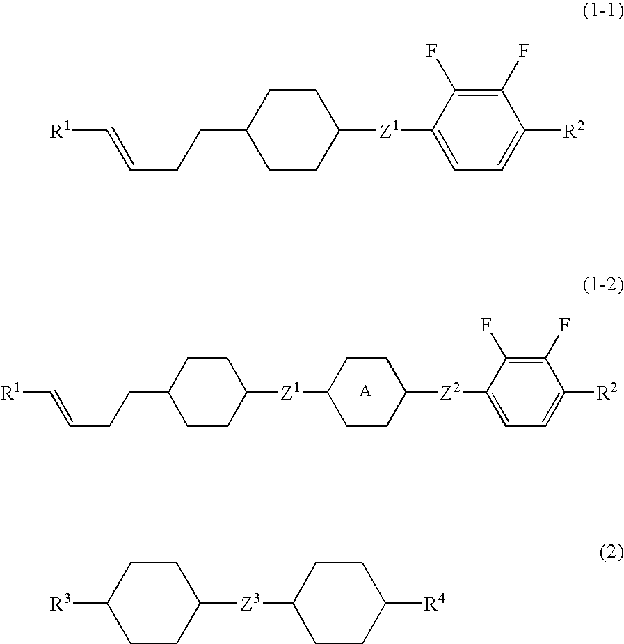
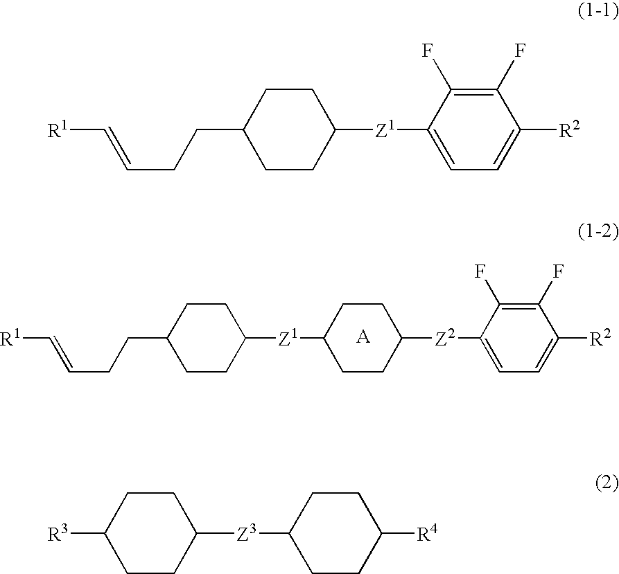
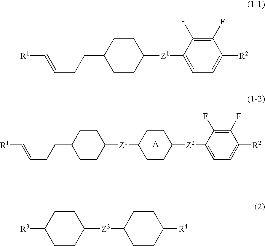
1V2-HB(2F,3F)-O2(1-1-1)10%1V2-HB(2F,3F)-O4(1-1-1)10%1V2-H2B(2F,3F)-O2(1-1-2)10%1V2-H2B(2F,3F)-O4(1-1-2)9%1V2-HHB(2F,3F)-O2(1-2-1-1)7%1V2-HHB(2F,3F)-O4(1-2-1-1)8%1V2-HBB(2F,3F)-O2(1-2-1-2)6%2-HH-5(2-1)10%3-HH-4(2-1)15%3-HH-5(2-1)10%3-HH-V1(2-1)5%

NI=72.3° C.; Tc≦−20° C.; Δn=0.084; Δ∈=−3.6; Vth=2.06 V; η=17.7 mPa·s; VHR-1=99.1%; VHR-2=98.1%; VHR-3=97.9%

example 2

[0087]The composition of Example 2 has a high maximum temperature of a nematic phase, a large negative dielectric anisotropy and a small viscosity, as compared to the composition of Comparative Example 2.

1V2-HB(2F,3F)-O2(1-1-1)10%1V2-HB(2F,3F)-O4(1-1-1)9%1V2-H2B(2F,3F)-O2(1-1-2)10%1V2-H2B(2F,3F)-O4(1-1-2)9%1V2-HHB(2F,3F)-O2(1-2-1-1)7%1V2-HHB(2F,3F)-O4(1-2-1-1)7%1V2-HBB(2F,3F)-O2(1-2-1-2)7%3-HH-V(2-1)10%3-HH-V1(2-1)10%V-HHB-1(3-1)7%V2-HHB-1(3-1)6%3-HB-O2(—)4%5-HB-O2(—)4%

NI=80.9° C.; Tc≦−20° C.; Δn=0.100; Δ∈=−3.6; Vth=2.14 V; η=18.8 mPa·s; VHR-1=99.0%; VHR-2=98.3%; VHR-3=98.1%

example 3

[0088]The composition of Example 3 has a high maximum temperature of a nematic phase and a small viscosity, as compared to the composition of Comparative Example 3.

1V2-HB(2F,3F)-O2(1-1-1)10%1V2-HB(2F,3F)-O3(1-1-1)9%1V2-HB(2F,3F)-O4(1-1-1)9%1V2-H2B(2F,3F)-O2(1-1-2)10%1V2-H2B(2F,3F)-O4(1-1-2)9%1V2-HHB(2F,3F)-O2(1-2-1-1)3%1V2-HH2B(2F,3F)-O2(1-2-2-1)7%1V2-HH2B(2F,3F)-O4(1-2-2-1)6%1V2-HB2B(2F,3F)-O2(1-2-2-2)5%1V2-HB2B(2F,3F)-O4(1-2-2-2)5%2-HH-3(2-1)11%3-HH-V(2-1)9%3-HH-V1(2-1)7%

NI=73.0° C.; Tc≦−20° C.; Δn=0.095; Δ∈=−4.4; Vth=1.87 V; η=18.8 mPa·s; VHR-1=98.9%; VHR-2=98.0%; VHR-3=97.7%


PUM


Abstract

A liquid-crystal composition which satisfies at least one of properties including a high upper-limit temperature for the nematic phase, low lower-limit temperature for the nematic phase, low viscosity, high optical anisotropy, negatively high permittivity anisotropy, high specific resistance, high stability to ultraviolet, and high stability to heat or has a proper balance between at least two of those properties. The liquid-crystal composition comprises a first ingredient comprising at least one compound selected among compounds represented by the formulae (1-1) and (1-2) and a second ingredient comprising at least one compound selected among compounds represented by the formula (2) and has negative permittivity anisotropy. For example, R1, R2, R3, and R4 each is C1-12 alkyl; Z1, Z2, and Z3 each is a single bond or —(CH2)2—; and ring A is 1,4-cyclohexylene or 1,4-phenylene.

Description

TECHNICAL FIELD[0001]The present invention relates to a liquid crystal composition suitable for use in an active matrix (AM) device, and an AM device containing the composition. More specifically, the invention relates to a liquid crystal composition having a negative dielectric anisotropy, and also relates to a device of an in-plane switching (IPS) mode or a vertical alignment (VA) mode containing the composition.BACKGROUND ART[0002]In a liquid crystal display device, classification based on an operating mode of liquid crystals includes phase change (PC), twisted nematic (TN), super twisted nematic (STN), electrically controlled birefringence (ECB), optically compensated bend (OCB), in-plane switching (IPS), vertical alignment (VA), and so forth. Classification based on a driving mode of the device includes a passive matrix (PM) and an active matrix (AM). PM is further classified into static, multiplex and so forth, and AM is classified into a thin film transistor (TFT), a metal in...

Claims


Application Information

Patent Timeline
IPC IPC(8): C09K19/02C09K19/30
CPCC09K19/3001C09K19/3003C09K19/42C09K2019/0407Y10T428/10C09K2019/123C09K2019/301C09K2019/3016C09K2019/0451C09K2323/00C09K19/30
Inventor HATTORI, NORIKATSUFUJITA, HIROAKI
Owner JNC CORP
Why Eureka
Try Eureka