Ultrasound imaging apparatus and method for processing ultrasound image

a technology of ultrasound imaging and ultrasound image, applied in the field of ultrasound imaging apparatus, can solve the problems of occurrence of tracking miss, degradation of tracking accuracy, and similar errors, and achieve the effect of accurate evaluation of tissue motion and simple operation

Active Publication Date: 2009-10-29
TOSHIBA MEDICAL SYST CORP +1
View PDF12 Cites 19 Cited by
  • Summary
  • Abstract
  • Description
  • Claims
  • Application Information

AI Technical Summary

Benefits of technology

[0017]An object of the present invention is to provide an ultrasound imaging apparatus that, in a process of tracking a region of interest, can accurately evaluate the motion of tissue included in the region of interest by correcting a tracking position with a simple operation even if the tracking position deviates, and also provide a method for processing an ultrasound image.

Problems solved by technology

However, in the method according to the related art, there is a problem of occurrence of a tracking miss within one heartbeat (Problem 1).
Moreover, there is a problem of degradation of the tracking accuracy in the case of tracking over a plurality of heartbeats (Problem 2).
However, since an error occurs in an estimated movement vector obtained by tracking in the forward direction and the tracking in the forward direction deviates, an error similarly occurs in an estimated movement vector at the time of tracking through the time phase T0 in the opposite direction.
In this case, it is difficult to distinguish from a waveform pattern in which systolic failure occurs due to an ischemic heart disease or the like.
In any event, it becomes difficult to accurately evaluate the normal pattern.
Therefore, such correction requires time and is not easy.
As for Problem 2, in general, tracking for long time results in accumulation of errors and easy deviation of the tracking.
Moreover, if movement of a subject due to breathing, etc. or movement of an ultrasound probe occurs during data acquisition, drift components are also accumulated.

Method used


Image

  • Ultrasound imaging apparatus and method for processing ultrasound image
  • Ultrasound imaging apparatus and method for processing ultrasound image
  • Ultrasound imaging apparatus and method for processing ultrasound image

Examples


first embodiment

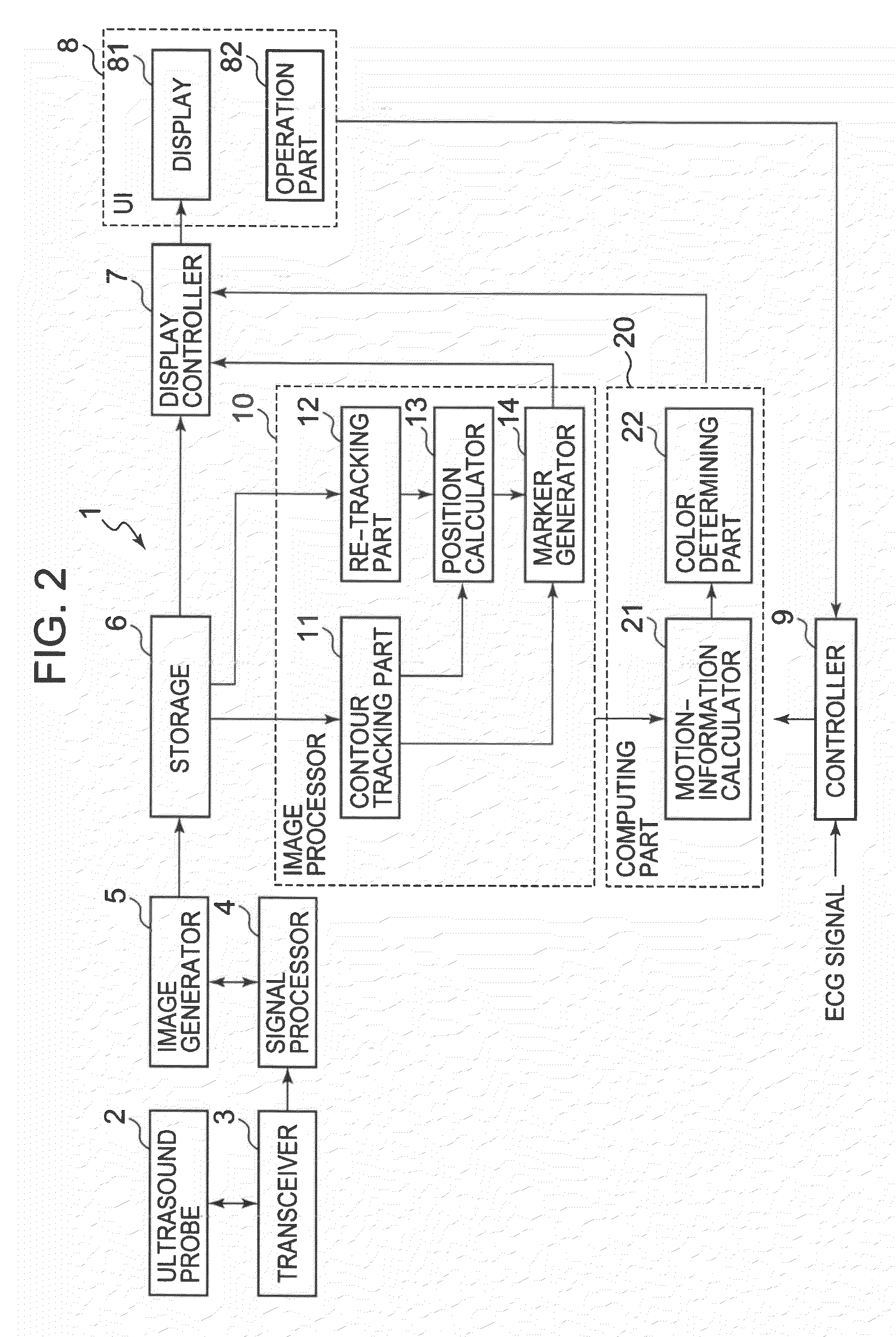
[0032]An ultrasound imaging apparatus according to a first embodiment of the present invention will be described with reference to FIG. 2. FIG. 2 is a block diagram illustrating the ultrasound imaging apparatus according to the first embodiment of the present invention.

[0033]An ultrasound imaging apparatus 1 according to the first embodiment includes an ultrasound probe 2, a transceiver 3, a signal processor 4, an image generator 5, a storage 6, a display controller 7, a user interface (UI) 8, a controller 9, an image processor 10, and a computing part 20. Moreover, an ultrasound image processing apparatus may be composed of the storage 6, the display controller 7, the user interface (UI) 8, the image processor 10, and the computing part 20.

[0034]As the ultrasound probe 2, a 1D array probe having a plurality of ultrasound transducers aligned in a predetermined direction (a scanning direction) or a 2D array probe having a plurality of ultrasound transducers two-dimensionally arranged...

second embodiment

[0120]Next, an ultrasound imaging apparatus according to a second embodiment of the present invention will be described. The above first embodiment describes the case that the ST process is executed once within one heartbeat and tracking of the contour position deviates in a certain time phase (time phase T1). The second embodiment describes a case of executing the ST process for a plurality of heartbeats. Since the configuration of the ultrasound imaging apparatus according to the second embodiment is the same as that of the ultrasound imaging apparatus I according to the first embodiment, the operation of the ultrasound imaging apparatus according to the second embodiment will be described.

(Step S01)

[0121]First, the operator designates a plurality of heartbeats (from the time phase T0 to the time phase Tend) by using the operation part 82. When the plurality of heartbeats are designated, information representing from the time phase T0 to the time phase Tend is outputted from the u...

third embodiment

[0130]Next, an ultrasound imaging apparatus according to a third embodiment of the present invention will be described with reference to FIGS. 7 through 10. FIGS. 7 through 10 are schematic views for illustrating the process performed by the ultrasound imaging apparatus according to the third embodiment. The abovementioned first embodiment and second embodiment describe without particularly limiting the site of the contour to which re-tracking is applied. In the third embodiment, re-tracking is executed only on an area to which a correction has been applied. This makes it possible to reduce the time required for re-tracking. Since the configuration of the ultrasound imaging apparatus according to the third embodiment is the same as that of the ultrasound imaging apparatus 1 according to the first embodiment, the operation of the ultrasound imaging apparatus according to the third embodiment will be described. In FIGS. 7 through 10, a total contour 300 is schematically shown. Further...


PUM


Abstract

In time phases except a first time phase, a contour tracking part tracks the position of a region of interest based on image data acquired in each of the time phases. A re-tracking part receives correction of the position of the region of interest in a second time phase, and obtains the position of the corrected region of interest in and after the second time phase based on the image data acquired in and after the second time phase. From position information of the region of interest in and before the second time phase and position information of the corrected region of interest in and after the second time phase, a position calculator obtains position information of the region of interest in all the time phases. A computing part obtains motion information of a tissue within the region of interest based on the position information of the region of interest.

Description

BACKGROUND OF THE INVENTION[0001]1. Field of the Invention[0002]The present invention relates to an ultrasound imaging apparatus capable of acquiring an ultrasound image representing a subject with ultrasound waves and capable of evaluating a motional state of the subject by using the ultrasound image, and also relates to a method for processing an ultrasound image.[0003]2. Description of the Related Art[0004]It is very important to objectively and quantitatively evaluate the function of body tissue such as the myocardium of the heart when diagnosing the body tissue. For example, a quantitative evaluation method based on image data representing the heart that is acquired by an ultrasound imaging apparatus is proposed.[0005]As an example, a technique of tracking using local pattern matching on a two-dimensional ultrasound image or a three-dimensional ultrasound image to calculate local wall-motion information such as displacement and strain of the myocardium (referred to as Speckle T...

Claims


Application Information

Patent Timeline
Patent Type & Authority Applications(United States)
IPC IPC(8): A61B8/14
CPCA61B8/0883A61B8/0891A61B8/13A61B8/463A61B8/469G06T2207/30048A61B8/5284G01S7/52042G01S7/52071G06T7/204G06T2207/10132A61B8/483G06T7/248
Inventor ABE, YASUHIKOKAWAGISHI, TETSUYAISHII, KATSUHISA
Owner TOSHIBA MEDICAL SYST CORP
Why Eureka
Try Eureka