Method and System for Cryoablation Treatment

a technology of cryoablation and treatment method, which is applied in the field of cryosurgical treatment method and system, can solve the problems of vapor lock effect, cloud of condensate, and current cooling system and method based on the use of liquid nitrogen as a means to cool a miniature probe tip,

Active Publication Date: 2009-10-29
CRYOMEDIX
View PDF19 Cites 57 Cited by
  • Summary
  • Abstract
  • Description
  • Claims
  • Application Information

AI Technical Summary

Benefits of technology

[0012]In addition to the liquid refrigerant container, the system also includes a cryoprobe. In detail, this cryoprobe includes a hollow, substantially tubular-shaped vacuum shell having a proximal end and a distal end. A cryotip that is formed with a liquid-tight chamber is attached to the distal end of the vacuum shell. And, a cold inlet line extends through the vacuum shell from its proximal end to its distal end to establish fluid communication with the chamber of the cryotip. Similarly, a return line extends proximally from the chamber of the cryotip, and back through the vacuum shell, to establish fluid communication between the chamber of the cryotip and the proximal end of the cryoprobe. Preferably, the outside diameters of the cryotip and of the vacuum shell are less than approximately 3 mm. As intended for the present invention, the vacuum shell is provided to thermally isolate the cold inlet line and the return line from contact with surrounding tissue while the cryoprobe is positioned for a procedure. Further, a turbulator can be positioned in the chamber of the cryotip to assist in the movement of liquid refrigerant through the cryoprobe.
[0015]Further, in the preferred embodiment of the present invention, the refrigerator will include a pressure vessel for holding a liquid cryogen. A portion of the cold inlet line that connects the container in fluid communication with the cryoprobe will then be coiled and submerged in the liquid cryogen. For the present invention, the liquid cryogen is preferably liquid nitrogen having a temperature in a range between −180° C. and −150° C. at a pressure in a range between 0.5 and 3.0 MPa, that will cool the liquid refrigerant to Tmin.

Problems solved by technology

This enormous increase in volume results in a “vapor lock” effect when the mini-needle of the cryoprobe gets “clogged” by the gaseous nitrogen.
This produces a cloud of condensate upon exposure to the atmospheric moisture in the operating room and requires frequent refilling or replacement of the liquid nitrogen storage tank.
For these and other similar type systems, cryosurgical practice shows that current cooling systems and methods that are based on the use of liquid nitrogen as a means to cool a miniature probe tip are not practicably feasible.
Nitrous oxide and carbon dioxide cooling systems, however, are not able to achieve the temperature and cooling power provided by liquid nitrogen systems.
However, because of an insufficiently low operating temperature combined with relatively high initial pressure, cryosurgical applications are strictly limited.
Stated differently, these heat exchanger systems are not compatible with the desired miniature size of probe tips that must be less than at least 3 mm in diameter.
In review, systems using liquid nitrogen as a means to cool a miniature probe tip are subject to “vapor lock.” On the other hand, systems that use highly pressurized gas mixtures in order to achieve the Joule-Thomson effect cannot provide operating temperatures lower than about −90° C. Thus, they are not desirable for many cryosurgical procedures.

Method used


Image

  • Method and System for Cryoablation Treatment
  • Method and System for Cryoablation Treatment
  • Method and System for Cryoablation Treatment

Examples


Embodiment Construction

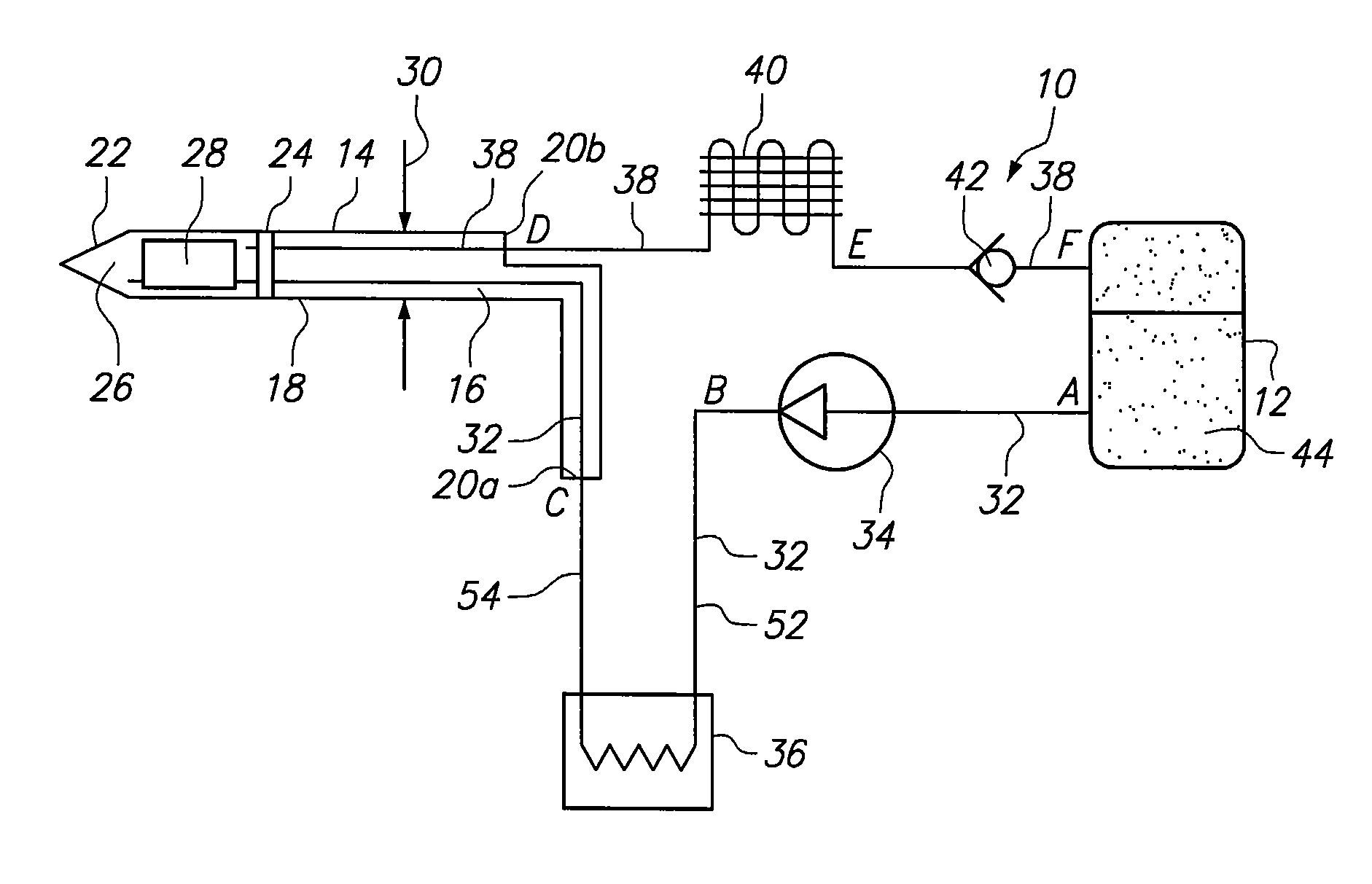
[0025]Referring initially to FIG. 1, a system for performing a cryosurgical procedure in accordance with the present invention is shown and is generally designated 10. As shown, the system 10 essentially includes a liquid container 12 and a cryoprobe 14. In detail, the cryoprobe 14 includes a substantially tubular shaped vacuum shell 16 having a distal end 18 and a proximal end 20. For purposes to be disclosed in greater detail below, the proximal end 20 may be bifurcated into separate proximal ends 20a and 20b. In any event, the cryoprobe 14 will also include a cryotip 22 that is affixed to a plug 24 at the distal end 18 of the vacuum shell 16. Structurally, the cryotip 22 is formed with a liquid-tight chamber 26, and a turbulator 28 may be positioned inside the liquid-tight chamber 26. As indicated in FIG. 1, the outside diameter 30 of the cryoprobe 14 is substantially the same for both the vacuum shell 16 and the cryotip 22 and is, preferably, less than 3 mm.

[0026]FIG. 1 also sho...


PUM


Abstract

A system and a method for its use are provided to cool a cryotip at the distal end of a probe for a cryosurgical procedure. In particular, the cryotip is cooled by a liquid refrigerant to cryogenic temperatures in order to perform a cryosurgical procedure on biological tissue. The system is closed-loop, and during transit of the liquid refrigerant through the entire system, the liquid refrigerant always remains in a liquid state at a relatively low pressure.

Description

[0001]This application claims the benefit of U.S. Provisional Patent Application Ser. No. 61 / 047,496, filed Apr. 24, 2008.FIELD OF THE INVENTION[0002]The present invention pertains generally to systems and methods for performing a cryosurgical procedure. More particularly, the present invention pertains to systems and methods that use a probe having a cryotip for cooling biological tissues to cryogenic temperatures. The present invention is particularly, but not exclusively, useful as a closed-loop system wherein a liquid refrigerant remains in a liquid state as it is cycled through the system between its source and the cryotip of a probe.BACKGROUND OF THE INVENTION[0003]A probe that is to be used for cryosurgery must be designed with an optimally small shape and size to achieve selective cooling of biological tissues. The cryosurgical system must also be designed to provide reliable cooling of the part of the cryoprobe (i.e. the cryotip) that will be in direct thermal contact with ...

Claims


Application Information

Patent Timeline
Patent Type & Authority Applications(United States)
IPC IPC(8): A61B18/02
CPCA61B18/02A61B2018/0262A61B2018/00041
Inventor BABKIN, ALEXEI V.LITTRUP, PETER J.NYDAM, WILLIAM J.
Owner CRYOMEDIX
Why Eureka
Try Eureka