Windmill utilizing a fluid driven pump

a technology of fluid driven pump and wind turbine, which is applied in the direction of fluid coupling, electric generator control, greenhouse gas reduction, etc., to achieve the effect of reducing structural materials, reducing costs, and efficient use of wind energy

Inactive Publication Date: 2009-11-05
PLANT JR WILLIAM R
View PDF18 Cites 28 Cited by
  • Summary
  • Abstract
  • Description
  • Claims
  • Application Information

AI Technical Summary

Benefits of technology

[0009]According to the present invention, a device is provided which meets the aforementioned requirements and needs in the prior art. Specifically, the device according to the present invention provides an apparatus for efficiently using wind energy, for a range of wind speed and conditions, and uses minimal structural materials for a wind powered apparatus. Also, the apparatus can produce electricity when any of a plurality of electrical generators is disabled or cannot be used, and can be incrementally expanded in power output capacity.

Problems solved by technology

From the foregoing, it is seen that it is a problem in the art to provide a device meeting the above requirements.

Method used


Image

  • Windmill utilizing a fluid driven pump
  • Windmill utilizing a fluid driven pump
  • Windmill utilizing a fluid driven pump

Examples


Embodiment Construction

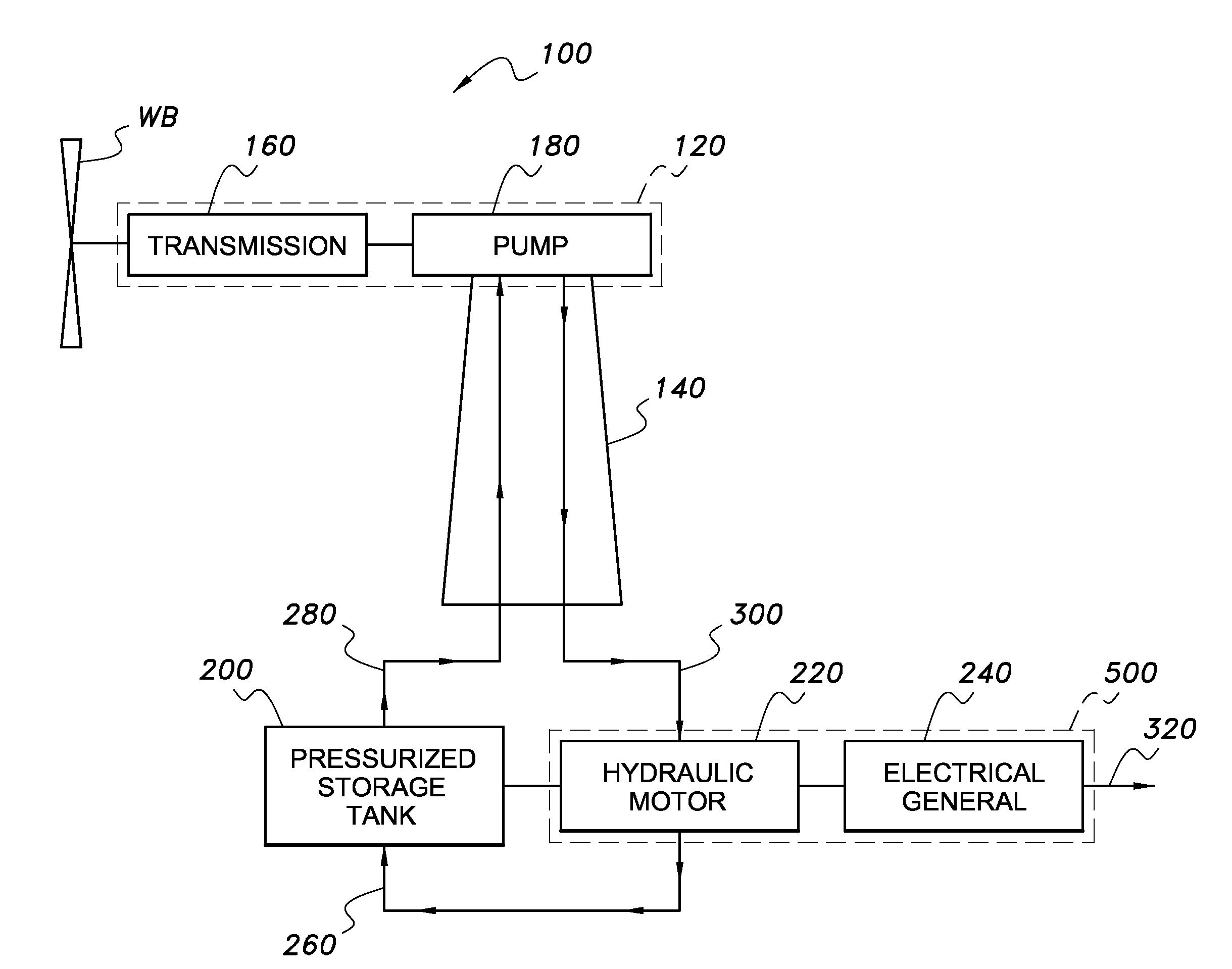
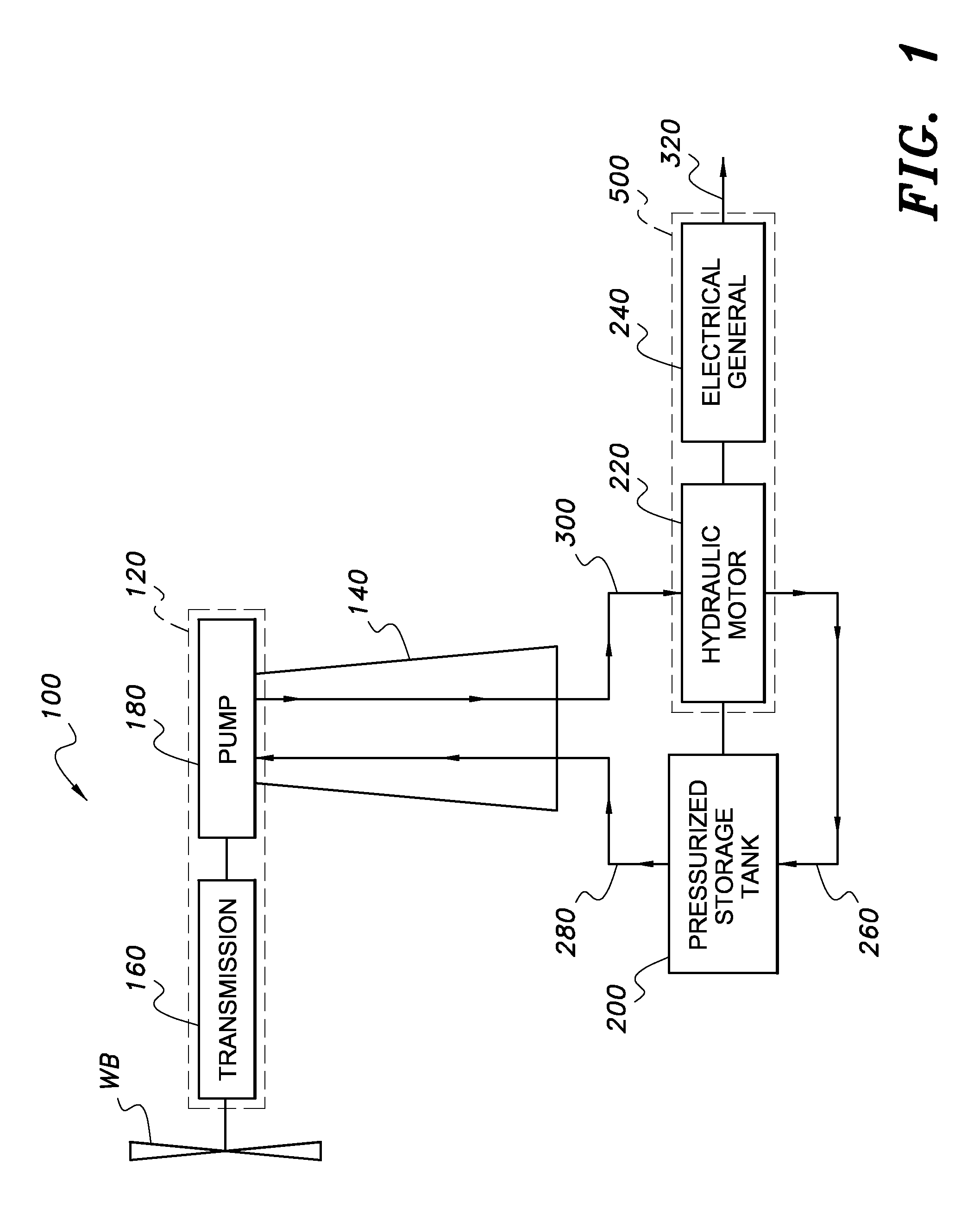
[0017]FIG. 1 is schematic side view of a windmill 100 utilizing a hydraulic pump 180, the windmill including a blade or plurality of blades WB, a housing 120, and a support tower 140. The windmill blades WB are driven by air flow to rotate, which in turn drives a mechanical transmission mechanism 160. The transmission 160 is connected to drive the pump 180, producing high pressure output fluid via a high pressure oil line 300, to a hydraulic motor 220.

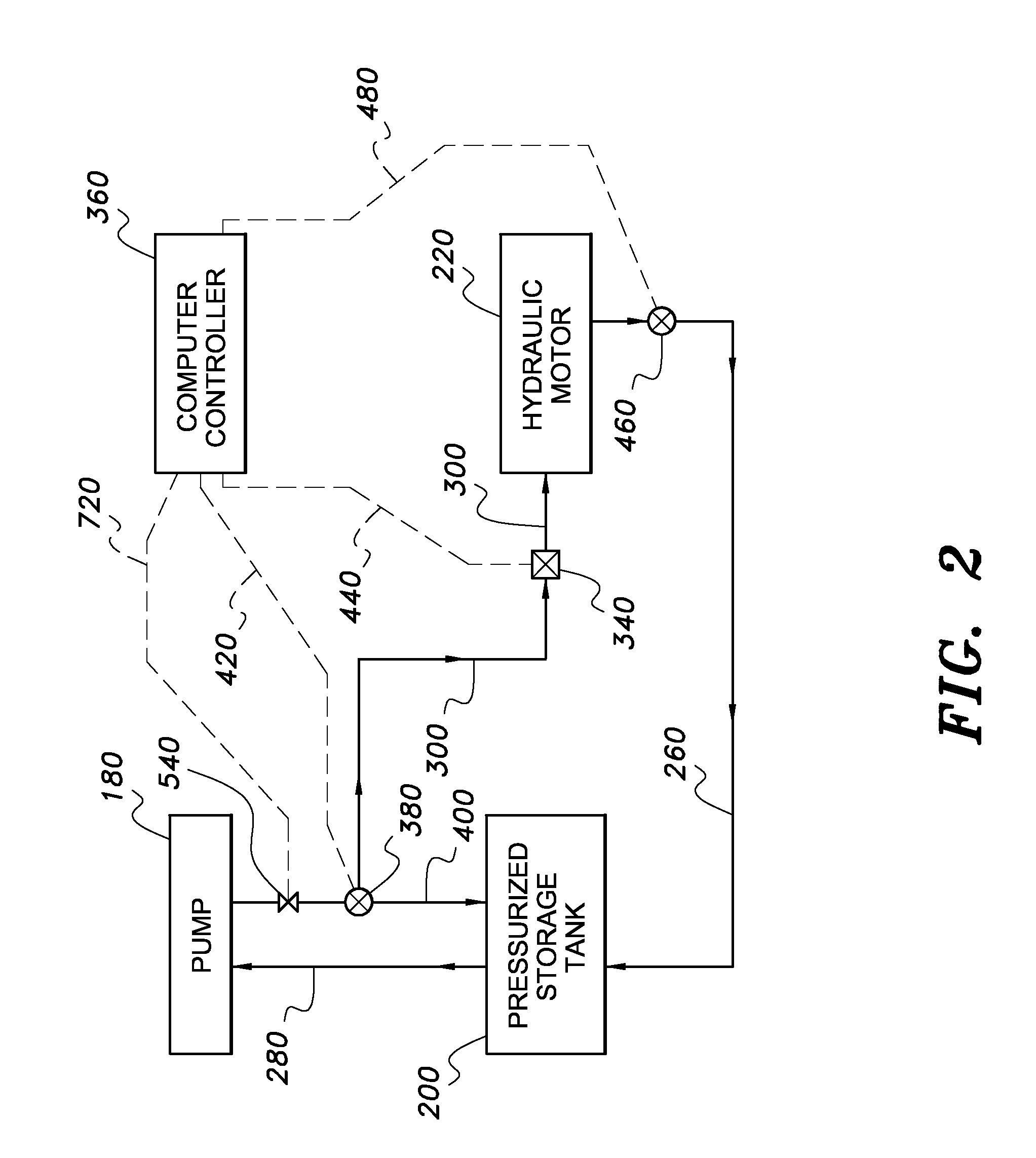
[0018]In FIG. 1, only a single generator unit 500 is shown, but as depicted in FIG. 3 in the preferred embodiment there are a plurality of such units. In operation, upon startup, as the wind propels the propeller-driven pump 180 the hydraulic fluid circulates freely until a pre-set pressure is achieved, upon which a pressure switch (for example, pressure sensor 540 as shown in FIG. 2) triggers a controller to actuate a valve or valves to divert all the fluid pressure to the first generator unit 500. The first such generator unit 500 is...


PUM


Abstract

A windmill apparatus includes tower, a tower-mounted hydraulic pump driven by windmill blades, and hydraulic lines connected to a ground storage tank and to a number of separate generator units. Each generator unit includes a hydraulic pump and an electrical generator. In operation, upon startup, as the wind propels the propeller-driven pump the hydraulic fluid circulates freely until a pre-set pressure is achieved, upon which a diverter valve diverts all the fluid pressure to the first generator unit. When the first generator unit is powered sufficiently to achieve a stable output voltage, a subsequent one of the remaining generator units is powered up until its output voltage is stabilized, with this process continuing as long as there is a surplus of hydraulic power available to power up additional units to take full advantage of all of the available wind power.

Description

CROSS REFERENCE TO RELATED APPLICATIONS[0001]Not applicable.STATEMENT REGARDING FEDERALLY SPONSORED RESEARCH OR DEVELOPMENT[0002]Not applicable.FIELD OF THE INVENTION[0003]The present invention relates generally to an apparatus for producing electrical power from wind energy. More particularly, this invention is directed to an apparatus for producing electrical power from wind energy using a plurality of generator sets arranged in stages.BACKGROUND OF THE INVENTION[0004]In U.S. Pat. No. 7,183,664 to McClintic, an advanced wind turbine design is shown which includes a wind powered rotary blade arrangement which powers a hydraulic pump. The pump pressurizes a hydraulic fluid which powers a hydraulic motor on the ground. The hydraulic motor powers an electrical generator, producing power.[0005]U.S. Pat. No. 4,496,847 to Parkins shows a power generator using wind energy, including a pump, a turbine, and an electric generator. Additional turbines are possible according to this patent.[00...

Claims


Application Information

Patent Timeline
Patent Type & Authority Applications(United States)
IPC IPC(8): F03D9/00H02P9/04
CPCY02E10/725F03D9/00F03D9/17F03D9/25F03D9/28Y02E10/72Y02E60/16Y02E70/30Y02P80/10
Inventor PLANT, JR., WILLIAM R.
Owner PLANT JR WILLIAM R
Why Eureka
Try Eureka