

Liquid jet apparatus and printing apparatus
a technology of liquid jet and printing machine, which is applied in the direction of printing, other printing machines, etc., can solve the problems of large power consumption, difficulty in layout, and large mounting area on the circuit board
- Summary
- Abstract
- Description
- Claims
- Application Information
AI Technical Summary
Benefits of technology
Problems solved by technology
Method used
Image

Examples
first embodiment
[0052]a liquid jet printing apparatus using a liquid jet apparatus of the invention will hereinafter be explained.
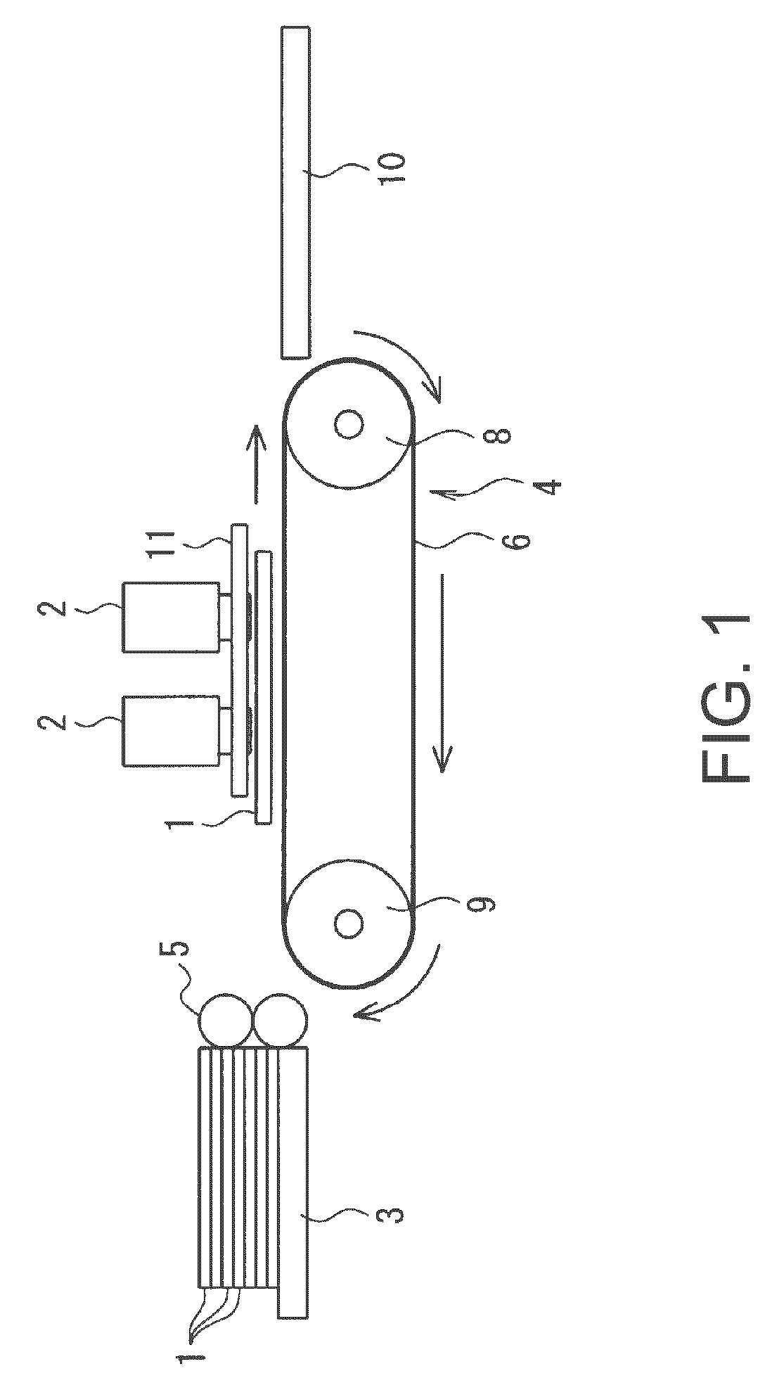
[0053]FIG. 1 is a schematic configuration diagram of the liquid jet printing apparatus of the first embodiment, and in FIG. 1, in the line head-type printing apparatus, a print medium 1 is conveyed from the left to the right of the drawing in the arrow direction, and printed in a printing area during the conveying operation.
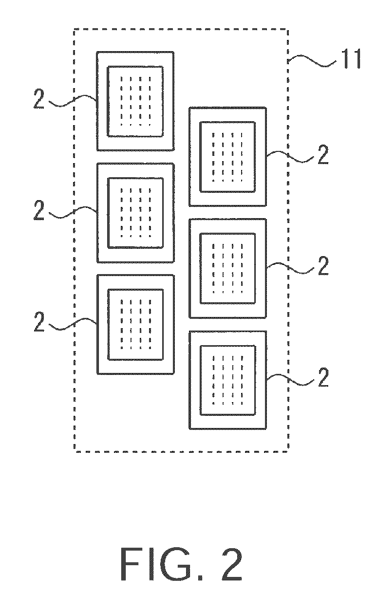
[0054]A reference numeral 2 shown in FIG. 1 denotes six liquid jet heads disposed above a conveying line of the print medium 1, which are fixed individually to a head fixing plate 11 in such a manner as to form two lines in the print medium conveying direction and to be arranged in a direction perpendicular to the print medium conveying direction. FIG. 2 is a plan view of the liquid jet head 2. The liquid jet head 2 is provided with a number of nozzles, and the surface thereof is called a nozzle surface.
[0055]A line head extending over the entire leng...
second embodiment
[0085]Also in the second embodiment, since it becomes possible to reduce the difference in voltage between the drive signal COM and the charge source power supply voltage VHV, it becomes possible to reduce the loss and the heat generation.
[0086]As described above, according to the second embodiment, since it is arranged that the power supply voltage generation circuits 27 are alternating-current voltage power supply circuits, or the voltage control circuits 28 are alternating-current voltage control circuits, it is suitable for realizing the power supply voltage control circuit 21, in addition to the advantage of the first embodiment.
[0087]A third embodiment of the liquid jet printing apparatus using the liquid jet apparatus of the invention will hereinafter be explained using FIGS. 12 and 13. All of the schematic configuration, control apparatus, drive signals, switching controller, and drive circuits of the liquid jet apparatus of the third embodiment are substantially the same as...
fourth embodiment
[0094]In contrast, by disposing the diode D31 for preventing back-flow on the output side of the bootstrap circuit 30 as in the fourth embodiment, the discharge of the electric charge from the actuator 22 as a charge-discharge actuator can be prevented, thus the variation in the drive signal COM can be suppressed and prevented.
[0095]As described above, according to the fourth embodiment, since the diode D31 for preventing back-flow is disposed on the output side of the bootstrap circuit 30, the waveform of the drive signal COM can be maintained.
[0096]A fifth embodiment of the liquid jet printing apparatus using the liquid jet apparatus of the invention will hereinafter be explained using FIGS. 16 and 17. All of the schematic configuration, control apparatus, drive signals, switching controller, and drive circuits of the liquid jet apparatus of the fifth embodiment are substantially the same as shown in FIGS. 1 through 8 of the first embodiment described above. FIG. 16 shows the powe...
PUM
 Abstract
Description
Claims
Application Information