Stereoscopic image display apparatus

a stereoscopic image and display apparatus technology, applied in the field of stereoscopic image display apparatus, can solve the problems of limitation of observing position in the y-axis direction, inability to display a stereoscopic image, and inability to use special tools such as glasses

Inactive Publication Date: 2009-11-05
PANASONIC CORP
View PDF6 Cites 30 Cited by
  • Summary
  • Abstract
  • Description
  • Claims
  • Application Information

AI Technical Summary

Benefits of technology

[0021]The stereoscopic image display apparatus according to the present invention reduces color misregistration of images associated with chromatic aberration and is therefore capable of displaying high-resolution, wide-viewing-angle, and bright images.

Problems solved by technology

Therefore, approaches of using special tools such as glasses cannot be employed except for special applications.
The parallax barrier method and the lenticular lens array method have a problem in that there is a limitation on the observing position in the Y-axis direction.
However, the method cannot deal with situations where the right and left eyes rotate around the X axis with respect to the screen, and therefore cannot display a stereoscopic image.
Usually, when a two-dimensional image is displayed with a stereoscopic image display apparatus in which a lenticular lens array is used, the resolution of the two-dimensional image deteriorates.

Method used


Image

  • Stereoscopic image display apparatus
  • Stereoscopic image display apparatus
  • Stereoscopic image display apparatus

Examples


embodiment 1

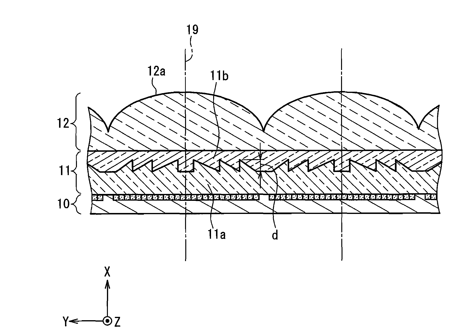
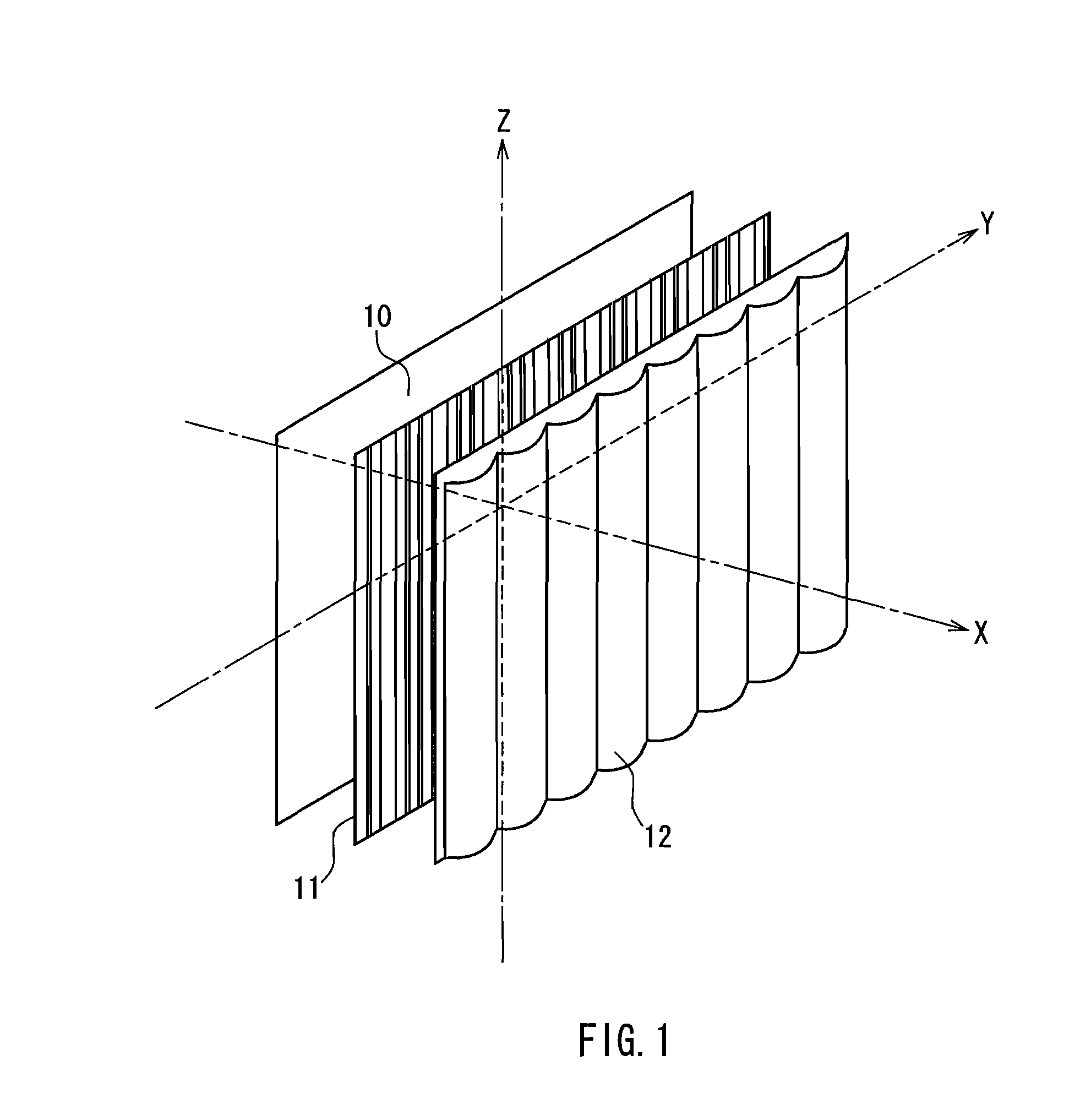
[0044]FIG. 1 schematically shows the configuration of a stereoscopic image display device according to Embodiment 1. Reference numeral 10 denotes an image display section formed by synthesizing a plurality of original images from different viewing points, 11 denotes a difffraction element array, and 12 denotes a lenticular lens array. In FIG. 1, the components are illustrated separately. However, a part or all of the components may be in close contact with each other, or may be spaced apart from each other by a predetermined distance. The shape of the lenticular lens array 12 and the shape of the diffraction element array 11 can be optimized in accordance with the arrangement of the components. As shown in FIG. 1, a vertical-direction axis and a horizontal-direction axis that are parallel to the image display section are referred to respectively as the Z axis and the Y axis, and an axis orthogonal to the Z axis and the Y axis is referred to as the X axis. In FIG. 1, a plurality of v...

example 1

[0064]An acrylic lenticular lens array 12 in which a plurality of cylindrical lenticular lenses were arranged parallel to the Z axis was used. The arrangement pitch of the lenticular lenses in the Y-axis direction was 2.54 mm ( 1 / 10 inches), and the focal length was 4 mm. Ten CCD cameras were disposed side by side at distances of 24 mm in the Y-axis direction, and images observed from the positions of the thus prepared ten viewing points were captured and synthesized to obtain a two-dimensional image. This two-dimensional image was printed with an inkjet printer and used as an image display section 10. A diffraction element array 11 and the lenticular lens array 12 were placed accurately on the image display section 10 without misalignment, and thus a stereoscopic image display apparatus was produced.

[0065]The diffraction element array 11 was produced by laminating a coating layer 11b made of a urethane acrylate ultraviolet-curable resin (the d-line refractive index after curing was...

example 2

[0068]A lenticular lens array 12 made of cycloolefin (ZEONEX480R, manufactured by Zeon Corporation) and in which a plurality of cylindrical lenticular lenses were arranged parallel to the Z axis was used. The arrangement pitch of the lenticular lenses in the Y-axis direction was 2.54 mm ( 1 / 10 inches), and the focal length was 4 mm. Ten CCD cameras were disposed side by side at distances of 24 mm in the Y-axis direction, and images observed from the positions of the thus prepared ten viewing points were captured and synthesized to obtain a two-dimensional image. This two-dimensional image was printed with an inkjet printer and used as an image display section 10. A diffraction element array 11 and the lenticular lens array 12 were placed accurately on the image display section 10 without misalignment, and thus a stereoscopic image display apparatus was produced.

[0069]A composite material containing a resin mainly composed of polycarbonate and zinc oxide (the composite material had a...


PUM


Abstract

A stereoscopic image display apparatus includes a synthetic image (10) formed by synthesizing a plurality of original images from different viewing points, a lens array (12), and a diffraction element array (11) having the same pitch as the lens array. The diffraction element array has a layer (11a) made of a first material and a layer (11b) made of a second material and includes a blazed diffraction grating pattern with a depth d that is formed at an interface between the layer made of the first material and the layer made of the second material. When the refractive index of the first material and the refractive index of the second material are expressed as functions of an arbitrary wavelength λ in the visible light range as n1(λ) and n2(λ), respectively, the depth d is substantially equal to λ/|n1(λ)−n2(λ)|. Thus, the stereoscopic image display apparatus reduces color misregistration of images associated with chromatic aberration and is therefore capable of displaying high-resolution, wide-viewing-angle, and bright images.

Description

TECHNICAL FIELD[0001]The present invention relates to a stereoscopic image display apparatus capable of displaying high-quality and wide-field images.BACKGROUND ART[0002]Displays and printed matters usually are constituted by a plurality of pixels arranged in a plane, but can be recognized by an observer as stereoscopic information (stereoscopic images) with some contrivance, and thus the realistic sensation and the recognition accuracy can be improved. The observer recognizes a relatively nearby object as three-dimensional by the difference between images seen by the right eye and the left eye. This difference between the images seen by the right eye and the left eye is called stereoscopic parallax. Conventionally, there have been proposed various types of stereoscopic image display apparatuses that use this property and project two images (images with stereoscopic parallax) from different viewing points onto the right and left eyes, respectively, thereby enabling the observer to r...

Claims


Application Information

Patent Timeline
Patent Type & Authority Applications(United States)
IPC IPC(8): G02B27/22G02B30/27
CPCG02B5/1885G03B35/18G02B27/2214G02B30/27
Inventor KORENAGA, TSUGUHIRO
Owner PANASONIC CORP
Why Eureka
Try Eureka