
Fiber optic cable and method of manufacturing the same

Inactive Publication Date: 2009-11-05
CORNING CABLE SYST LLC
View PDF20 Cites 48 Cited by
  • Summary
  • Abstract
  • Description
  • Claims
  • Application Information

AI Technical Summary

Benefits of technology

[0008]Also disclosed is a method of manufacturing a fiber optic cable using a control layer for creating a predetermined bond. The method includes the steps of providing at least one optical fiber and surrounding the optical fiber with a protective layer, and applying a control layer about at least a portion of the protective layer, wherein the control layer includes one or more apertures extending therethrough. The method also includes the steps of applying a cable jacket about the control layer, thereby creating a predetermined bond between the protective layer and the cable jacket. The concepts of the invention provide the craft with fiber optic cables that are quickly and easily accessible since a predictable predetermined bond is created, while still providing a robust cable design.

Problems solved by technology

A fiber optic cable without adequate water-blocking capability can undesirably subject the optical fibers therein to damage and / or create a duct for the flow of water along the length of the fiber optic cable.
However, the adhesive located between the cable jacket and the armor layer can make removal of the cable jacket time consuming and / or difficult.
Moreover, the bond strength between the cable jacket and the armor layer can be unpredictable.

Method used


Image

  • Fiber optic cable and method of manufacturing the same
  • Fiber optic cable and method of manufacturing the same
  • Fiber optic cable and method of manufacturing the same

Examples


Embodiment Construction

[0019]The present invention will now be described more fully hereinafter with reference to the accompanying drawings in which example embodiments of the invention are shown. Whenever possible, the same reference numerals are used throughout the drawings to refer to the same or like parts. However, this invention may be embodied in many different forms and should not be construed as limited to the embodiments set forth herein. These example embodiments are provided so that this disclosure will be both thorough and complete, and will fully convey the scope of the invention to those skilled in the art.

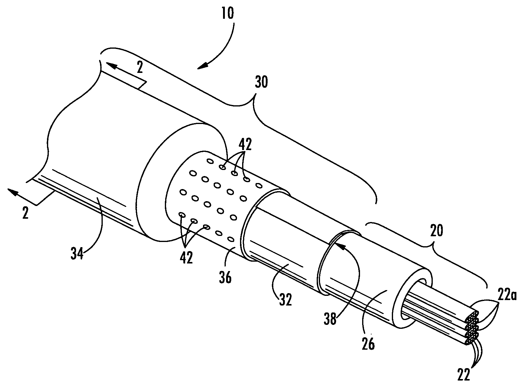
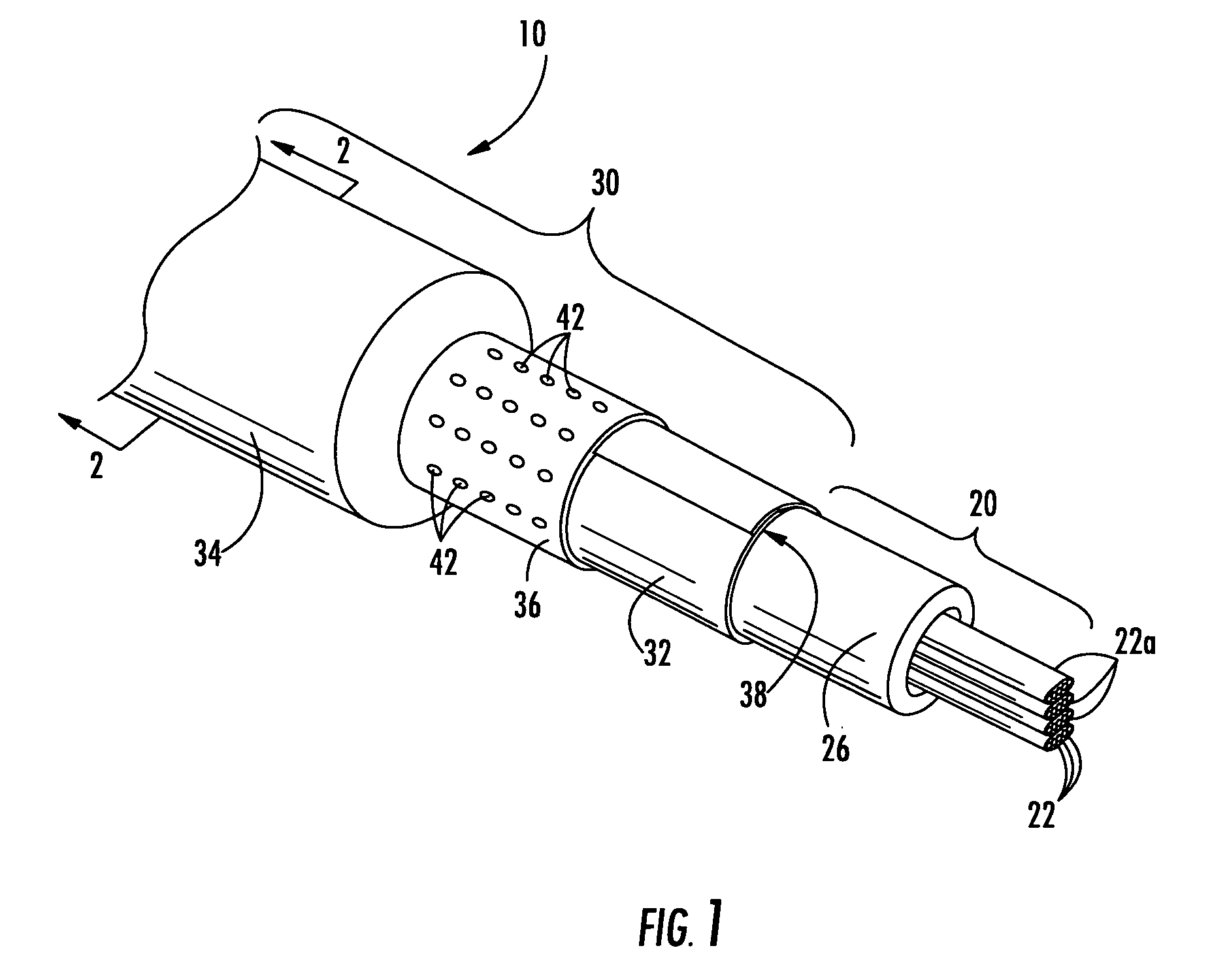
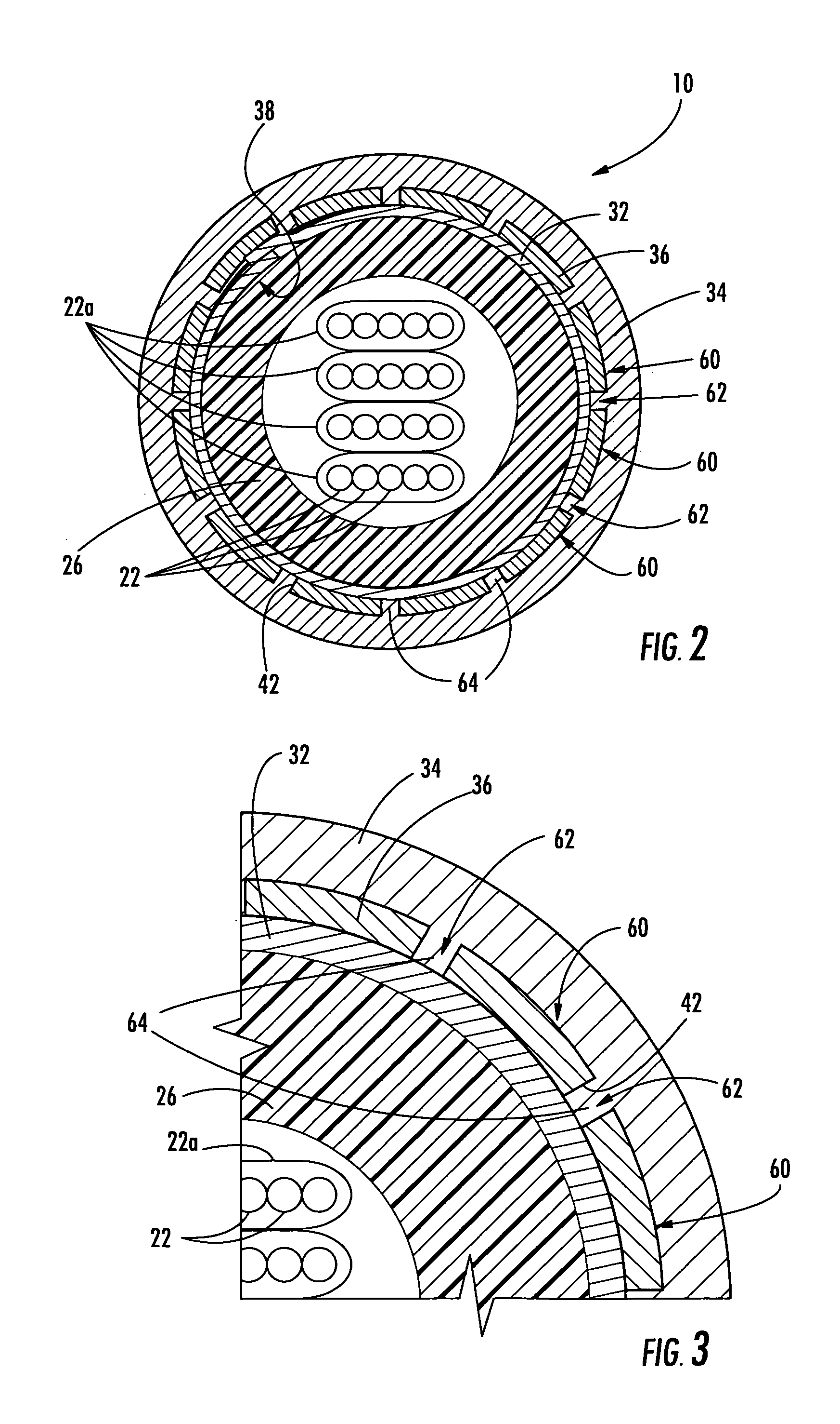
[0020]Referring now to FIG. 1, an explanatory fiber optic cable 10 according to one aspect of the present invention will be described. Fiber optic cable 10 generally includes a cable core section 20 and a jacket section 30, though it can also include various other sections, cable components, etc. Jacket section 30 includes a control layer 36 interposed between a portion of a protective la...


PUM

PropertyMeasurementUnit
Fractionaaaaaaaaaa
Temperatureaaaaaaaaaa
Sizeaaaaaaaaaa

Abstract

A fiber optic cable is that includes at least one optical fiber and a protective layer generally disposed about the optical fiber. A cable jacket surrounds an outer surface of the protective layer, and a control layer is interposed between a portion of the protective layer and a portion of the cable jacket. The control layer includes one or more apertures extending therethrough, thereby creating a predetermined bond between the protective layer and the cable jacket. By way of example, the protective layer is an armor layer, buffer tube, or other suitable cable component where a predetermined bond to the cable jacket is desired so the craft can easily remove a portion of the cable jacket. The plurality of apertures can have any suitable size, shape, and / or arrangement for influencing the desired bond strength. A method of manufacturing the fiber optic cable is also disclosed.

Description

BACKGROUND OF THE INVENTION[0001]1. Field of the Invention[0002]The present invention relates generally to fiber optic cables and methods for manufacturing the same. More particularly, the invention is directed fiber optic cables having a cable jacket with a predetermined bond characteristic and methods for manufacturing the same.[0003]2. Technical Background[0004]Fiber optic cables are used to transmit telephone, television, and computer data information in indoor and outdoor environments. Outside plant fiber optic cables are designed for use in the outdoor environment, and should be robust enough to withstand effects such as cable bending, twisting action, and attack by rodents. Thus, an outside plant fiber optic cable typically includes one or more cable components to enhance the robustness of the same. For instance, an outside plant fiber optic cable may include an armor layer generally disposed about the optical fiber for inhibiting moisture and / or rodents from reaching a cable...

Claims


Application Information

Patent Timeline
IPC IPC(8): G02B6/44C03C25/10
CPCG02B6/4486
Inventor LAIL, JASON C.
Owner CORNING CABLE SYST LLC
Learn More