Laser processing apparatus and laser processing method

a laser processing and laser processing technology, applied in the field of laser processing apparatus and laser processing method, can solve the problems of insufficient laser processing of objects and insufficient processing of objects, and achieve the effect of easy condensation

Inactive Publication Date: 2009-11-12
SUMITOMO ELECTRIC IND LTD
View PDF4 Cites 2 Cited by
  • Summary
  • Abstract
  • Description
  • Claims
  • Application Information

AI Technical Summary

Benefits of technology

[0007]The present invention has been developed to eliminate the problems described above. It is an object of the present invention to provide a laser processing apparatus having a structure for effectively processing an object to be processed and a laser processing method using the same.
[0012]In accordance with a laser processing apparatus according to the present invention, by arranging a condensing direction modifier between a condenser optical system and objects, as described above, a laser beam can be condensed at a condensed point that is different from the condensed point by the condenser optical system, according to the position where the laser beam arrives. Thus, even in a case where the surface to be processed of an object is present at a position different from the back focal point of the condenser optical system, the laser processing apparatus is capable of effectively condensing a laser beam onto the surface to be processed. Further, by arranging the condensing direction modifier, effective laser beam irradiation can be realized in a wide range, which enables effective laser beam processing of objects.
[0013]In a laser processing apparatus according to the present invention, a condensing direction modifier preferably has a uniform refractive index distribution. In this case, the thickness of the condenser optical system along the optical axis direction thereof is different according to the position where a laser beam from a mirror arrives. Thus, in a case where the refractive index of a condensing direction modifier is uniform while the thickness of a condenser optical system along the optical axis direction thereof is different according to the position where a laser beam is inputted, the laser beam that is outputted from the condensing direction modifier is condensed at a condensed point, the distance of which from the condenser optical system is different according to the input position. Further, the condensing direction modifier can be easily formed from a material, the refractive index of which is uniform, and a laser beam can be easily condensed at a position which is different from the position of the back focal plane of the condenser optical system.

Problems solved by technology

Accordingly, when an irradiation area (the surface to be processed) of an object is present at a position different from the back focal plane of the lens, since the surface to be processed is irradiated with a laser beam in a state where the laser beam is not condensed, the object may be insufficiently processed.
Further, in a case where the surface to be processed is not parallel with the back focal plane, the surface having an angle with respect to the back focal plane, since the irradiation intensity of a laser beam is smaller than on the back focal plane, this case also caused insufficient laser processing of an object.

Method used


Image

  • Laser processing apparatus and laser processing method
  • Laser processing apparatus and laser processing method
  • Laser processing apparatus and laser processing method

Examples


first embodiment

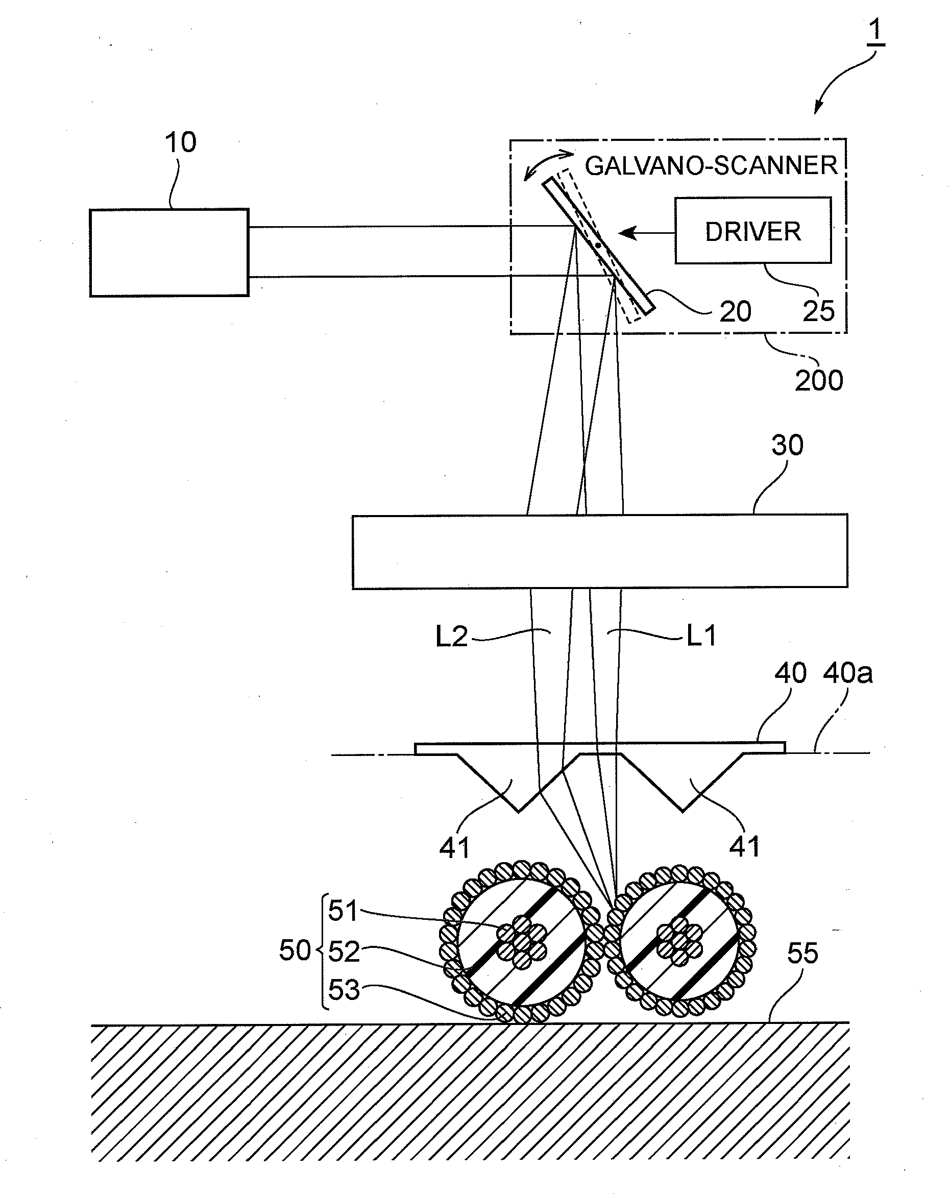
[0020]A laser processing apparatus and laser processing method according to a first embodiment will be described. FIG. 1 is a diagram illustrating a constitution in the first embodiment of a laser processing apparatus according to the present invention. The laser processing apparatus 1, shown in FIG. 1, processes the surfaces of objects to be processed 50 by irradiating the objects 50 with a laser beam. In concrete terms, the laser processing apparatus 1 comprises a laser light source 10, a galvano-scanner 200 as a scanning system, a lens 30 being a condenser optical system, a condensing direction modifier 40, and a common mount surface 55. The galvano-scanner 200 includes a galvano-mirror 20 and a driver 25 that changes the reflection angle of the galvano-mirror 20. The condensing direction modifier 40 has a first surface (the laser beam entrance surface) facing the lens 30 and a second surface (the laser beam exit surface) opposing the first surface, wherein a part (a part paralle...

second embodiment

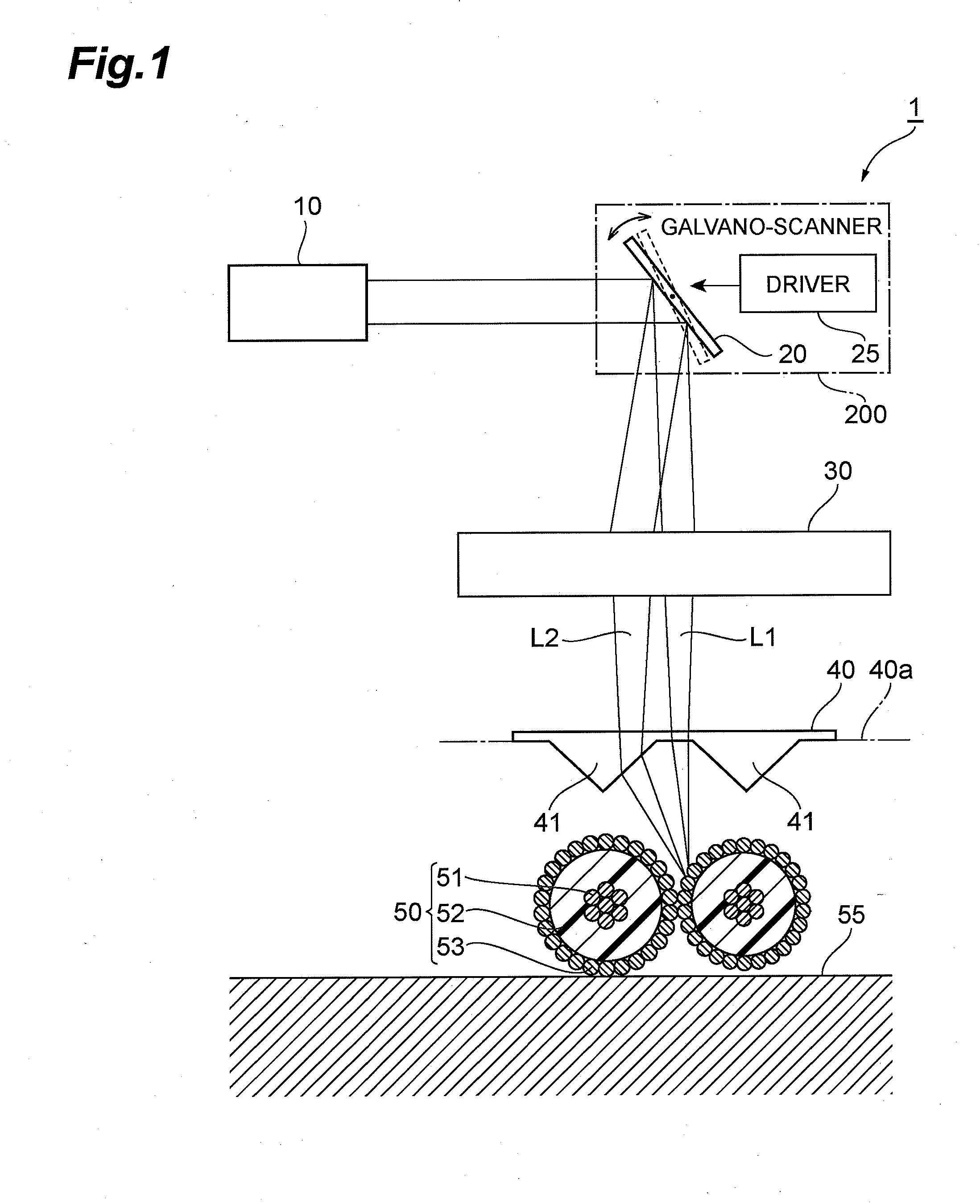
[0033]Next, a laser processing apparatus and a laser processing method in a second embodiment according to the present invention will be described. FIG. 2 is a diagram illustrating a constitution in the second embodiment of a laser processing apparatus according to the present invention. The laser processing apparatus 2, shown in FIG. 2, processes the surfaces of objects to be processed 50 by irradiating the objects 50 with a laser beam, the same as the laser processing apparatus 1 according to the first embodiment. In concrete terms, the laser processing apparatus 2 according to the second embodiment comprises a laser light source 10, a galvano-scanner 200 as a scanning system, a lens 30 being a condenser optical system, a condensing direction modifier 43, and a common mount surface 55. The galvano-scanner 200 includes a galvano-mirror 20 and a driver 25 that changes the reflection angle of the galvano-mirror 20. The condensing direction modifier 43 has a first surface (the laser b...

third embodiment

[0043]Next, a laser processing apparatus and laser processing method in a third embodiment according to the present invention will be described. FIG. 3 is a diagram illustrating a constitution in the third embodiment of a laser processing apparatus according to the present invention. The laser processing apparatus 3, shown in FIG. 3, processes, the same as in the foregoing first and second embodiments, the surfaces of processing objects 50 by irradiating the objects 50 with a laser beam. In concrete terms, the laser processing apparatus 3 according to the third embodiment comprises a laser light source 10, a galvano-scanner 200 as a scanning system, a lens 30 being a condenser optical system, a condensing direction modifier 46, and a common mount surface 55. The galvano-scanner 200 includes a galvano-mirror 20 and a driver 25 that changes the reflection angle of the galvano-mirror 20. The condensing direction modifier 46 has a first surface (the laser beam entrance surface) facing t...


PUM

PropertyMeasurementUnit
diameteraaaaaaaaaa
heightaaaaaaaaaa
refractive index distributionaaaaaaaaaa

Abstract

The present invention relates to a laser processing apparatus having a structure for effectively processing of objects by condensing a laser beam, and a laser processing method. A laser processing apparatus comprises a common mount surface on which plural objects are disposed in an array, a light source, a lens the reflection direction of which is changeable, and a condensing direction modifier. A laser beam from the light source arrives at the lens through a galvano-mirror. Herein, the galvano-mirror is arranged such that the reflection position thereof agrees with the front focal position of the lens. As the galvano-mirror reflects a laser beam toward the lens while the reflection direction is changed, the arriving position of the laser beam is scanned on the entrance surface of the lens. The condensing direction modifier modifies, according to the irradiation position of the laser beam arrived from the lens, an exit direction of the laser beam.

Description

BACKGROUND OF THE INVENTION[0001]1. Field of the Invention[0002]The present invention relates to a laser processing apparatus having a structure for desired processing of objects by the use of a laser beam, and a laser processing method.[0003]2. Related Background Art[0004]By irradiating a surface of an object to be processed with a laser beam, an irradiation area of the object to be processed can be processed. Such a laser beam processing is versatile. For example, FAYb-laser-marker LP-V series brochure, published by SUNX Limited in November 2005, No. CJ-LPV10-I-10 (Document 1), discloses a technology of a laser marker for printing on the surface of a processing object.SUMMARY OF THE INVENTION[0005]The present inventors have examined conventional laser processing apparatuses, and as a result, have discovered the following problems.[0006]That is, a conventional laser processing apparatus condenses a laser beam, in general, by using a condenser optical system, and processes an object...

Claims


Application Information

Patent Timeline
Patent Type & Authority Applications(United States)
IPC IPC(8): B23K26/04G02B3/00G02B3/08G02B5/04
CPCB23K26/06B23K2201/34B23K2201/32B23K26/0807B23K26/082B23K2101/32B23K2101/34
Inventor NAKAMAE, KAZUOKAKUI, MOTOKITAMAOKI, SHINOBU
Owner SUMITOMO ELECTRIC IND LTD
Why Eureka
Try Eureka