
Fluid ejecting apparatus

a technology of ejecting apparatus and ejecting chamber, which is applied in printing and other directions, can solve the problems of difficult to make the sealing member closely contact the entire area of the recording head, and difficult to make the capping device closely contact the recording head

Active Publication Date: 2009-11-12
SEIKO EPSON CORP
View PDF3 Cites 4 Cited by
  • Summary
  • Abstract
  • Description
  • Claims
  • Application Information

AI Technical Summary

Benefits of technology

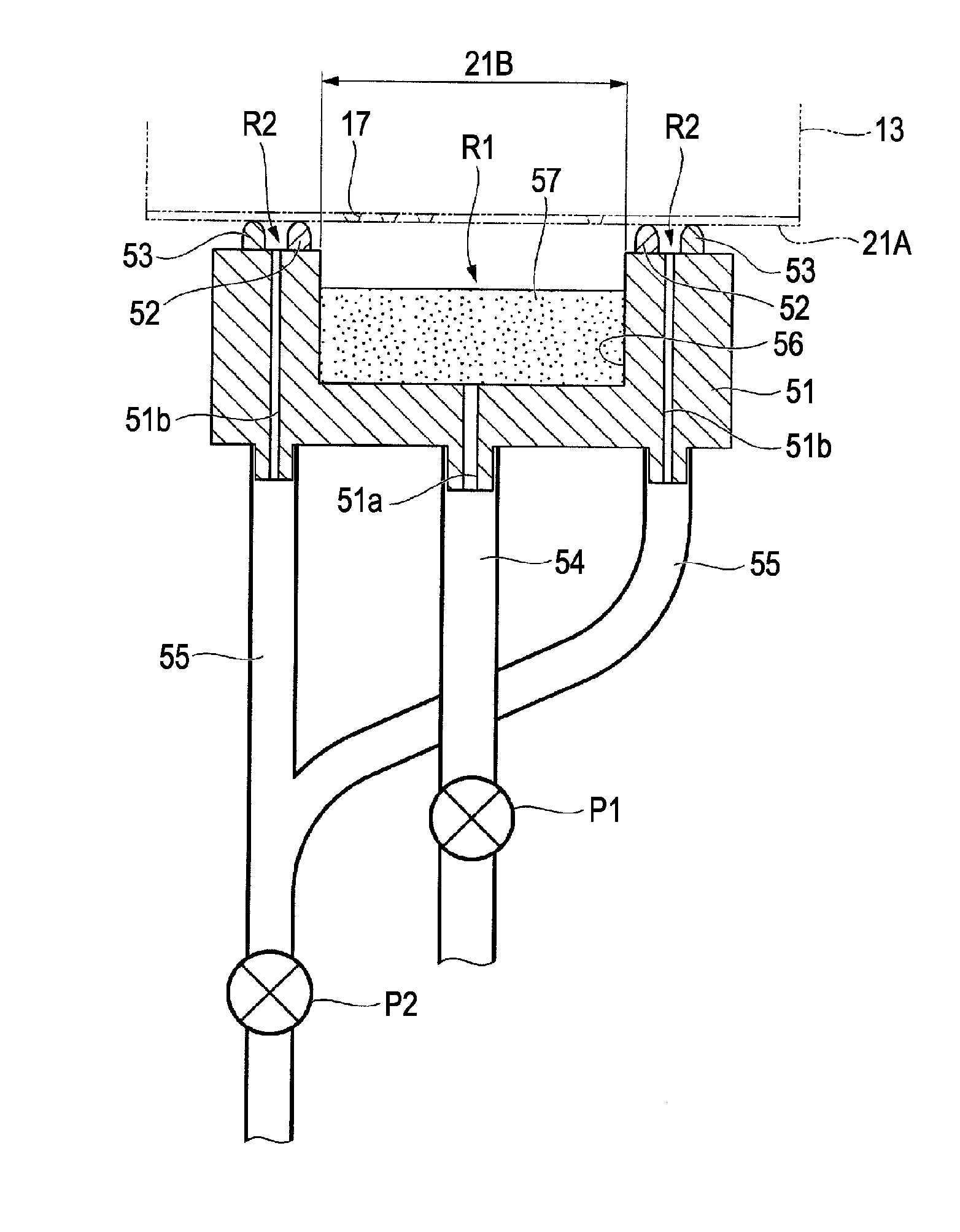
[0010]With the fluid ejecting apparatus according to the aspect of the invention, the second suction port serves to make the second space enter a negative pressure state so that the cap body is attracted to the ejection surface, whereby a close contact load for pressing the first contact member against the ejection surface is generated. Thus, the capping device can be made to closely contact the recording head and the first space surrounded by the first contact member can be reliably made to enter a negative pressure state, and fluid can be drained from the nozzles in the nozzle region, so that a maintenance operation can be smoothly performed. Moreover, because the capping device is made to closely contact the recording head with the negative pressure, capping device can be pressed against the recording head with a small load in an initial stage of capping operation, so that creep deformation of the first contact member and the second contact member can be reduced.
[0012]With this structure, because the second contact member surrounds the first contact member, a close contact load can be applied to the entire area of the first contact member. Thus, the first contact member can be made to closely contact the ejection surface of the ejection head with reliability.
[0014]With this structure, because a suction is performed on an end in a long axis direction of a long fluid ejection head such as a line head, a sufficient contact load is applied to the end of the head, so that the capping device can closely contact the head with reliability.
[0016]With this structure, the first contact member is prevented from being broken due to a contact load generated in the second space, so that the first space can be tightly closed with reliability. Thus, a suction force can be reliably applied to the nozzle region through the first suction port.
[0020]With this structure, because one suction device applies a suction force to the first and second suction ports, the structure of the fluid ejecting apparatus can be simplified.

Problems solved by technology

However, for example, when the capping device is used for a long recording head, such as a line head, it is difficult to make the sealing member closely contact the entire area of the recording head because of deflection or the like that is generated in long components.
Therefore, it may be difficult to make the capping device closely contact the recording head.

Method used


Image

  • Fluid ejecting apparatus
  • Fluid ejecting apparatus
  • Fluid ejecting apparatus

Examples


Embodiment Construction

[0033]Hereinafter, a fluid ejecting apparatus according to an embodiment of the invention is described with reference to the drawings. As necessary, components of the apparatus are shown in different scales in the drawings so that the components can be recognized. In the present embodiment, an ink jet printer is described as an example of the fluid ejecting apparatus according to the invention.

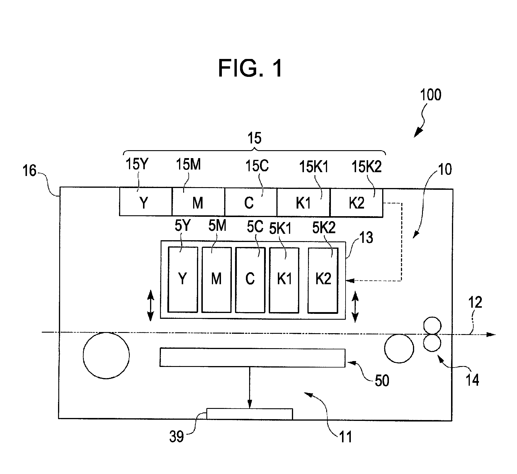
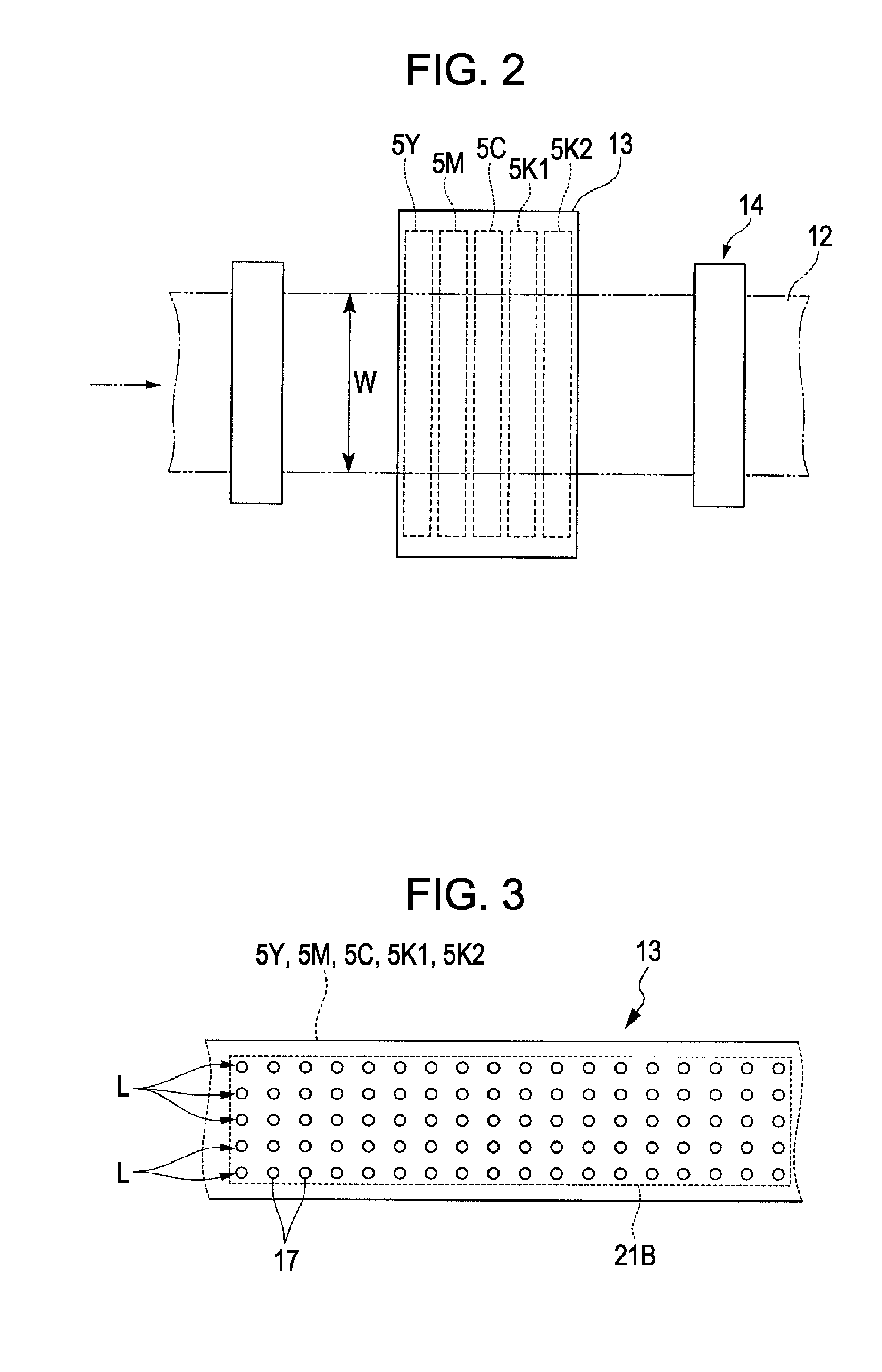
[0034]FIG. 1 is a schematic view of an ink jet printer (hereinafter, referred to as a printer 100) according to the present embodiment, FIG. 2 is a plan view of a region surrounding a recording head, and FIG. 3 is a plan view of an ejection surface of the recording head.

[0035]As shown in FIGS. 1 and 2, in the present embodiment, the printer 100 includes a recording section 10 that performs recording on a recording sheet 12 and a maintenance section 11 that performs a maintenance operation on the recording section 10.

[0036]The recording section 10 includes a recording head 13 (ejection head) th...


PUM


Abstract

A fluid ejecting apparatus includes an ejection head having an ejection surface with a nozzle region and a capping device that contacts the ejection surface. The capping device includes first and second contact members held by a cap body. When the first contact member contacts the ejection surface, a surface of the first contact member surrounds the nozzle region. The second contact member is formed in a closed frame-shape to be disposed outside a surface of the first contact member opposite the surface of the first contact member. The cap body includes first and second suction ports. The first suction port decompresses a first space formed between the first contact member and the ejection surface when the capping device contacts the ejection head. The second suction port decompresses a second space formed between the second contact member and the ejection surface when the capping device contacts the ejection head.

Description

CROSS-REFERENCE TO RELATED APPLICATION[0001]The entire disclosure of Japanese Patent Application No. 2008-123224, filed May 9, 2008 is expressly incorporated by reference herein.BACKGROUND[0002]1. Technical Field[0003]The present invention relates to a fluid ejecting apparatus.[0004]2. Related Art[0005]Fluid ejecting apparatuses have ejection heads from which various types of fluid are ejected onto recording media or the like. Typical examples of fluid ejecting apparatuses are ink jet recording apparatuses having ink jet recording heads (hereinafter referred to simply as recording heads). Ink jet recording apparatuses perform recording by ejecting droplets of liquid ink (fluid) from nozzles in the recording heads (ejection heads), allowing the droplets land on recording media, and thereby forming dots on the recording media.[0006]In the ink jet recording apparatuses, while ink is not being discharged, regions surrounding the nozzles are sealed so that ink in the nozzles does not dry...

Claims


Application Information

Patent Timeline
IPC IPC(8): B41J2/165
CPCB41J2/16508B41J2/16585B41J2/16532
Inventor HARADA, KOJI
Owner SEIKO EPSON CORP
Learn More