Formable bone plate, clamping apparatus, osteotomy system and method for reconstructing a bone

a technology of clamping apparatus and bone plate, which is applied in the field of small bone plate reconstruction, can solve the problems of pulling out the same and/or damage to the bone, and achieve the effect of improving surgical procedures and facilitating optimal clamping

Active Publication Date: 2009-11-12
SKELETAL DYNAMICS INC
View PDF27 Cites 155 Cited by
  • Summary
  • Abstract
  • Description
  • Claims
  • Application Information

AI Technical Summary

Benefits of technology

[0007]It is accordingly an object of the invention to provide a formable bone plate, a node clamping apparatus, an osteotomy system and a method for reconstructing a bone, which overcome the above-mentioned disadvantages of the heretofore-known devices of this general type and which allow a user to easily shape o

Problems solved by technology

Even in a case where the first node has been attached to the bone with a screw, the first clamp isolates the bending forces exerted by the rotatio

Method used


Image

  • Formable bone plate, clamping apparatus, osteotomy system and method for reconstructing a bone
  • Formable bone plate, clamping apparatus, osteotomy system and method for reconstructing a bone
  • Formable bone plate, clamping apparatus, osteotomy system and method for reconstructing a bone

Examples


first embodiment

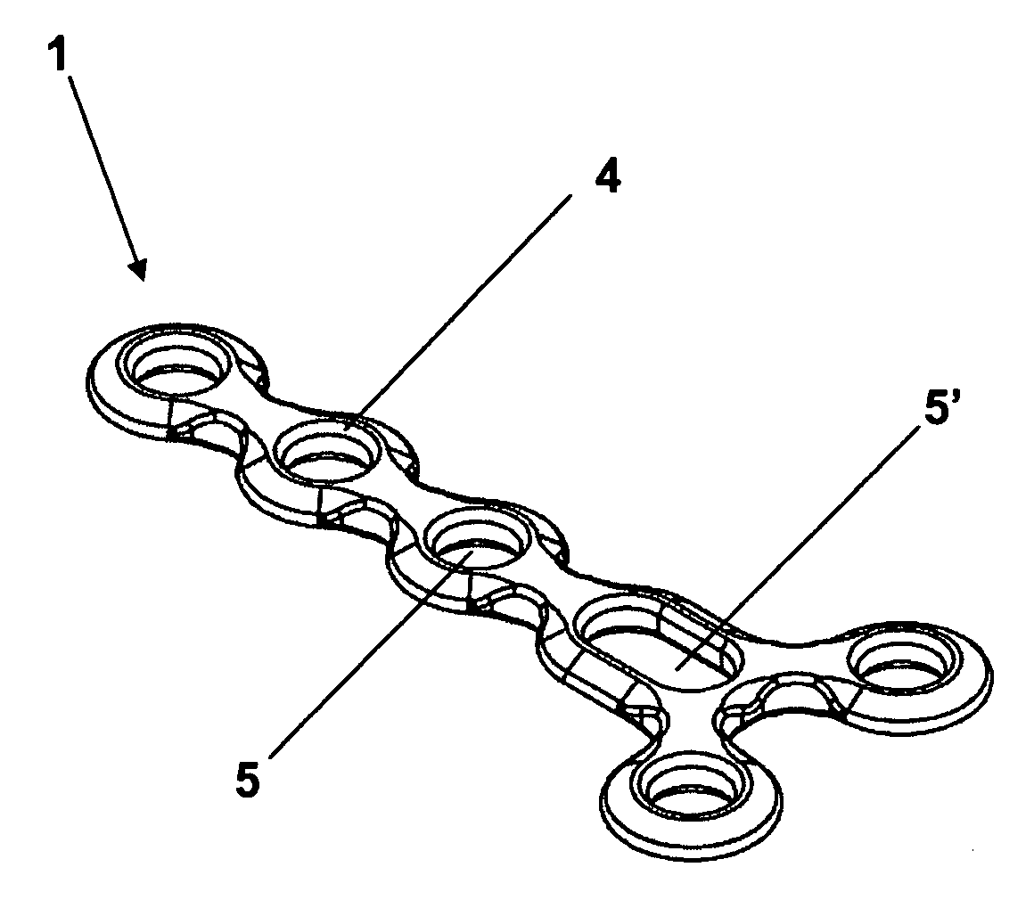
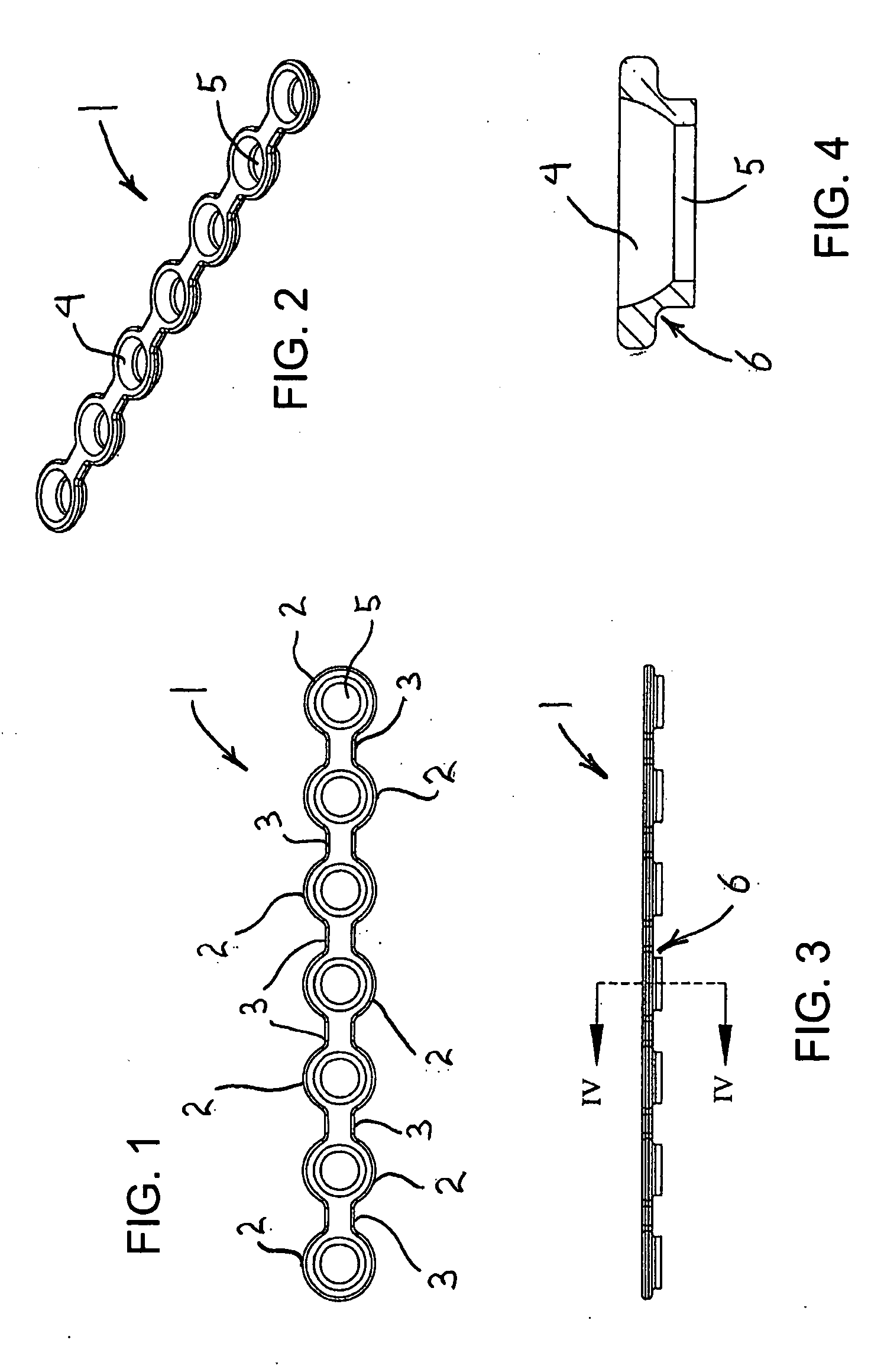
[0062]Referring now to the figures of the drawings in detail and first, particularly, to FIGS. 1-4 thereof, there is seen a bone plate 1 according to one particular embodiment of the invention, having a plate body with seven nodes 2 and webs or internodes 3, therebetween. However, this is not meant to be limiting, as the bone plate 1 may have more or fewer than seven nodes, as desired, and may be linear, T-shaped, L-shaped, Y-shaped, arched, curved or any combination of shapes, as will be discussed further below. The nodes 2 each have an inner surface 4, which can be spherical, aspherical, frustoconical, cylindrical or any other geometric shape as required for seating or engaging the complementarily shaped head of a screw, surrounding a hole 5 for permitting passage of the shaft of a screw 23, as is best seen in FIGS. 15 and 16. Each node 2 also has a clamp engagement section 6, as will be discussed further below.

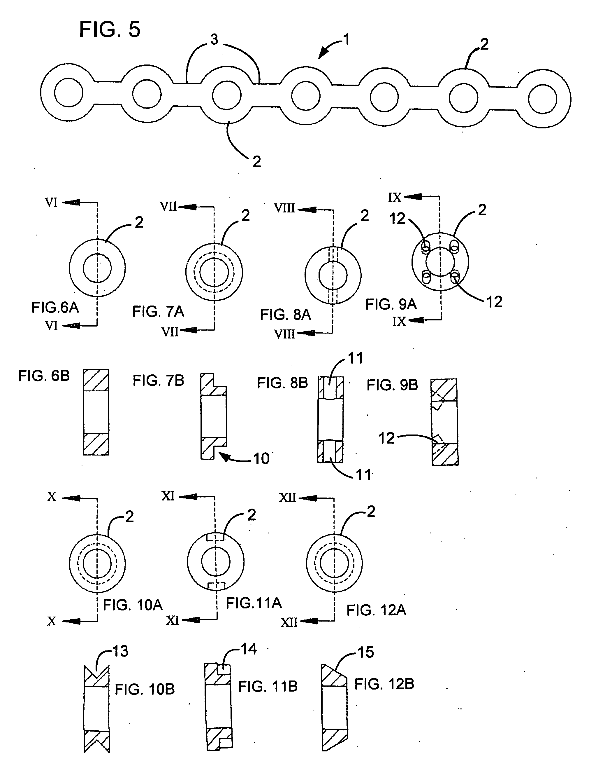
[0063]FIG. 5 shows a bone plate 1′ with nodes 2 and internodes or webs...

second embodiment

[0064]FIGS. 13A and 13B show bone plate 1 with nodes 2 and internodes or webs 3, inner surface 4, which can be spherical, aspherical, frusto-conical, cylindrical or any other geometric shape as required for seating or engaging the complementarily shaped head of a screw, surrounding a circular hole 5 or elongated slot 5′ for permitting passage of the shaft of a screw. FIG. 13C shows a cross section of a node 2 with an engagement section conformed by a convex annular or circumferential V-shaped radial projection 16. The engagement section is symmetrical which allows the plate to be used with its upper or lower surface, indistinctly, adjacent to the bone.

[0065]FIGS. 14A and 14B are respective top and bottom perspective views of a bone plate 1 according to one particular embodiment of the invention, having the nodes 2, the internodes 3, the inner surfaces 4 and the screw holes 5. The plate 1 can have a variety of shapes and / or geometries in accordance with the instant invention. For exa...


PUM


Abstract

A system and method are provided that use a formable bone plate and a clamping apparatus for small bone reconstruction. The formable bone plate includes a plate body having a plurality of nodes separated by internodes. Each node includes a hole formed therein for receiving a screw, wire, tack, or other fixation device screwed or placed into a bone. A clamp engages an engagement section of the node to facilitate bending of at least one of the internodes to contour the plate to the bone in-situ or ex-situ and when at least partly screwed to or not screwed to the bone.

Description

CROSS-REFERENCE TO RELATED APPLICATION[0001]The present application claims priority to the co-pending Provisional Patent Application No. 61 / 051,749, filed on May 9, 2008 and entitled “Formable Bone Plate, Clamping Apparatus, Osteotomy System And Method For Reconstructing A Bone”, which application is being incorporated herein, by reference, in its entirety.BACKGROUND OF THE INVENTION[0002]1. Field of the Invention[0003]The invention relates to a formable bone plate, a clamping apparatus, an osteotomy system and a method for small bone reconstruction. Such a plate, apparatus, system and method provide a surgeon with implants and instruments necessary to perform reconstructive bone surgery (osteotomies and fusions) of the small bones of the upper extremity or other parts of the human body, which could eventually include wrist, hand, maxillofacial, foot and ankle surgery.[0004]2. Description of the Related Art[0005]Typical formable bone plates are formed of nodes that provide for screw...

Claims


Application Information

Patent Timeline
IPC IPC(8): A61B17/56A61B17/84
CPCA61B17/1728A61B17/80A61B17/808A61B2019/304A61B17/8085A61B17/8897A61B17/8863A61B2090/034
Inventor ORBAY, JORGE L.NORMAN, THOMAS H.GARCIA DE QUEVEDO, WILLIAM
Owner SKELETAL DYNAMICS INC
Why Eureka
Try Eureka