
Multivariable control system

a control system and multi-variable technology, applied in adaptive control, process and machine control, instruments, etc., can solve the problems of complex computational demands, inability to adequately control cross-coupled multi-variable systems with such models, and inability to accurately control cross-coupled multi-variable systems. application of such technology has been limited to chemical process applications, so as to reduce the difference

Active Publication Date: 2009-11-12
RTX CORP
View PDF10 Cites 26 Cited by
  • Summary
  • Abstract
  • Description
  • Claims
  • Application Information

AI Technical Summary

Benefits of technology

"The patent describes a method and system for controlling a system with multiple variables. The system receives a set of limits, goals, and sensor feedback, and uses a mathematical model to predict the system's behavior. The system then adjusts the basepoint, or the desired values for the goals, to reduce any differences between the predicted and sensor feedback. This allows for smoother control of the system. The technical effects of this invention include improved control accuracy and efficiency, as well as reduced latency and improved responsiveness."

Problems solved by technology

In a cross-coupled system, it is not possible to change a single effector in isolation to affect only single goal or limit, as a change in one effector may affect a plurality of goals or limits.
Calculating effector commands in a cross-coupled multi-variable system can therefore be complex and computationally demanding, and it may be necessary to prioritize goals in order to meet all limits while best meeting a number of goals.
Cross-coupled multi-variable systems cannot be adequately controlled with such models.
While some existing model predictive control technology can address both cross-coupled multi-variable requirements while enforcing limits, application of such technology has been limited to chemical process applications, which require updates only once every several minutes.
Such a computational burden is not practical in a system, such as a vehicle control system, where updates may be required on the order of one hundred times per second.

Method used


Image

  • Multivariable control system
  • Multivariable control system
  • Multivariable control system

Examples


Embodiment Construction

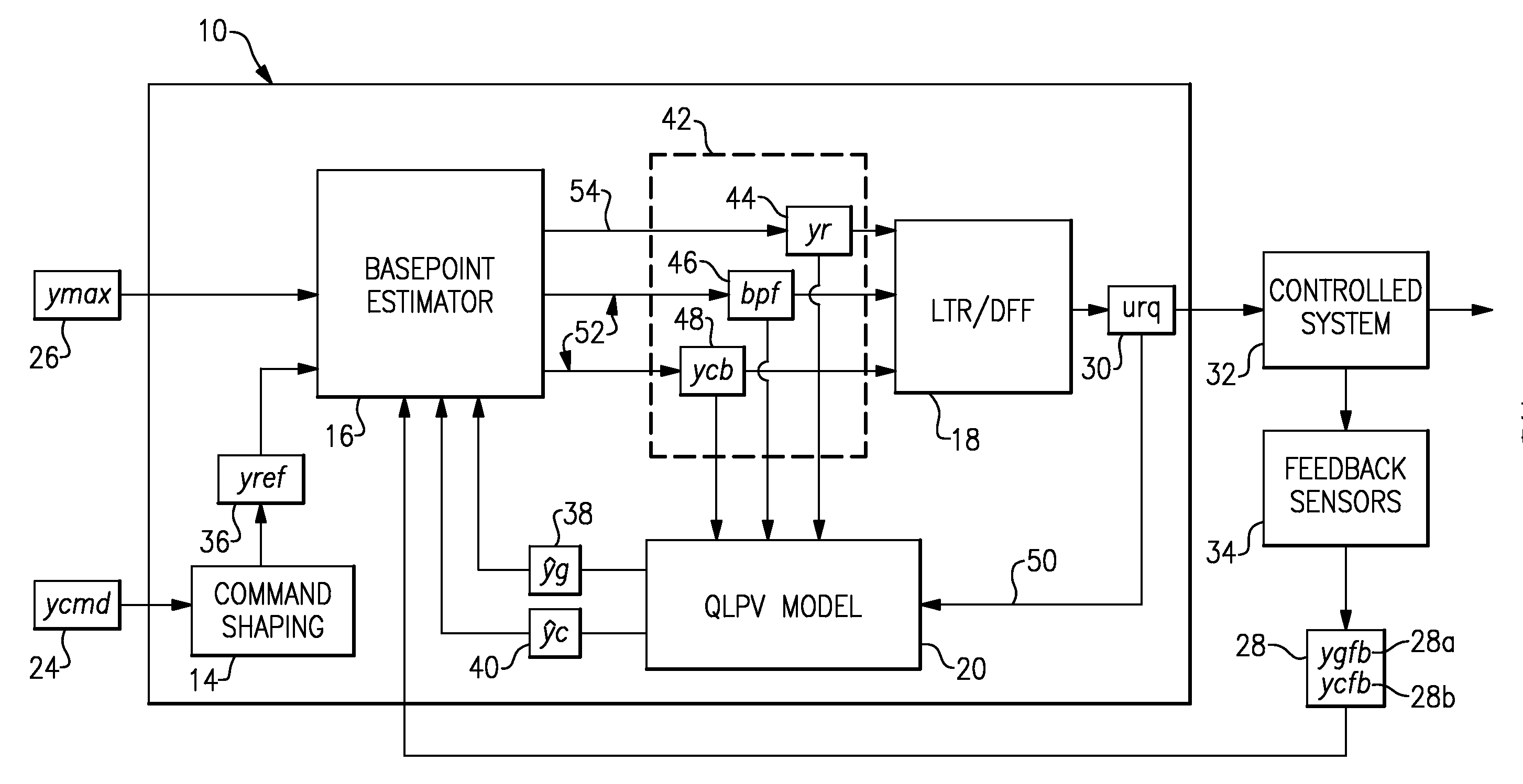
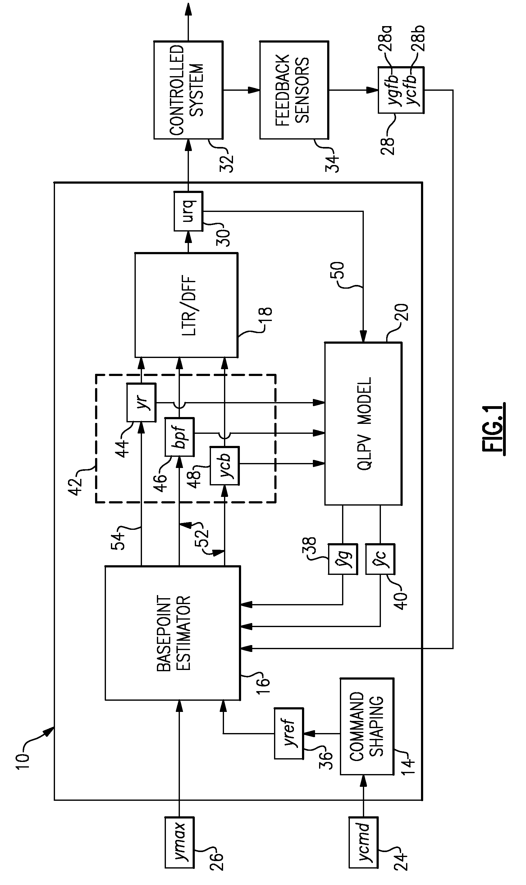
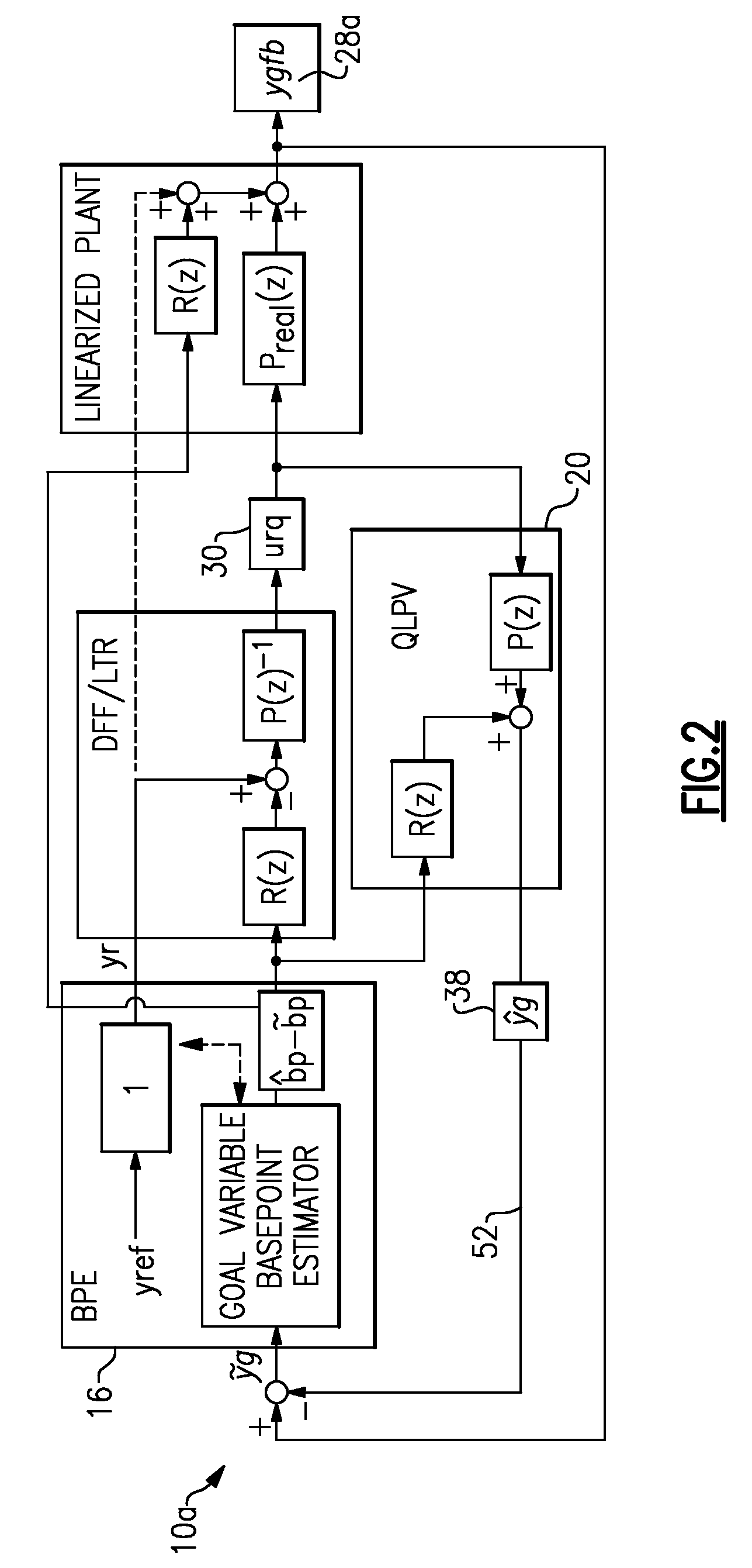
[0013]FIG. 1 schematically illustrates an example multivariable control system 10. The system 10 includes an optional command shaping module 14, a basepoint estimator 16, a loop transfer function recovery / dynamic feed forward (“LTR / DFF”) module 18, and a mathematical model 20. The mathematical model 20 is designed to predict behavior of a controlled system 32 and represents system dynamics of the controlled system 32. In the example of FIG. 1, the mathematical model 20 is a quasi-linear parameter varying (“QLPV”) model. However, it is understood that the mathematical model 20 would not have to be a QLPV model, and could be another type of model, such as a locally linearized model.

[0014]The system 10 is operable to receive a plurality of commands 24 (“ycmd”), a plurality of maximum or minimum values for limited variables, or “limits”26 (“ymax”), and feedback signals 28 (“ygfb” and “ycfb”) as inputs, and is operable to produce actuator requests 30 (“urq”) in response to those inputs. ...


PUM


Abstract

A method for controlling a multivariable system according to one non-limiting embodiment includes receiving a plurality of limits, receiving a first quantity of goals each having a desired value, and receiving sensor feedback. The method further includes estimating a basepoint in response to the first quantity of goals, the plurality of limits, and the sensor feedback, wherein the basepoint includes a set of values corresponding to an equilibrium point at which a predetermined amount of enabled limits are met and a second quantity of goals are fulfilled according to a goal prioritization scheme. Predicted values from a mathematical model are compared to the sensor feedback, and the estimated basepoint is selectively adjusted in response to a difference between the predicted values and the sensor feedback in order to reduce the difference.

Description

[0001]This invention was made with government support under Contract No.: N00019-02-C-3003 awarded by the Navy. The government may therefore have certain rights in this invention.BACKGROUND OF THE INVENTION[0002]This application relates to control systems, and more particularly to cross-coupled multivariable control systems.[0003]In control theory, a given control system may have a plurality of goals and a plurality of limits. Limits are inequality constraints on system dynamic variables. An example limit may be to prevent an engine temperature from exceeding a certain temperature in order to prevent meltdown or rapid deterioration. Another might be to prevent a rotor speed from exceeding a certain angular velocity to maintain structural integrity. An example goal may be to achieve a certain engine thrust level, such as a thrust of 10,000 pounds. While it is desirable to achieve goals, it is necessary to meet limits. A multivariable system may include a number of effectors that can ...

Claims


Application Information

Patent Timeline
Patent Type & Authority Applications(United States)
IPC IPC(8): G05B13/04
CPCG05B13/04
Inventor FULLER, JAMES W.
Owner RTX CORP
Learn More