Engine lubrication method

a technology of internal combustion engine and lubrication method, which is applied in the direction of pressure lubrication, lubricant mounting/connection, lubricant elements, etc., can solve the problems of insufficient horsepower output of four-cycle engines, difficult problems with four-cycle engines,

Inactive Publication Date: 2009-11-19
ETG
View PDF20 Cites 26 Cited by
  • Summary
  • Abstract
  • Description
  • Claims
  • Application Information

AI Technical Summary

Problems solved by technology

Electric motors unfortunately have limited applications due to power availability for corded products, and battery life and power availability for cordless devices.
When it comes to power tools such as line trimmers, chain saws and blower/vacuums, the use of four-cycle engines pose a very difficult problem.
Four-cycle engines tend to be too heavy for a given horsepower output and providing lubrica...

Method used


Image

  • Engine lubrication method
  • Engine lubrication method
  • Engine lubrication method

Examples


Embodiment Construction

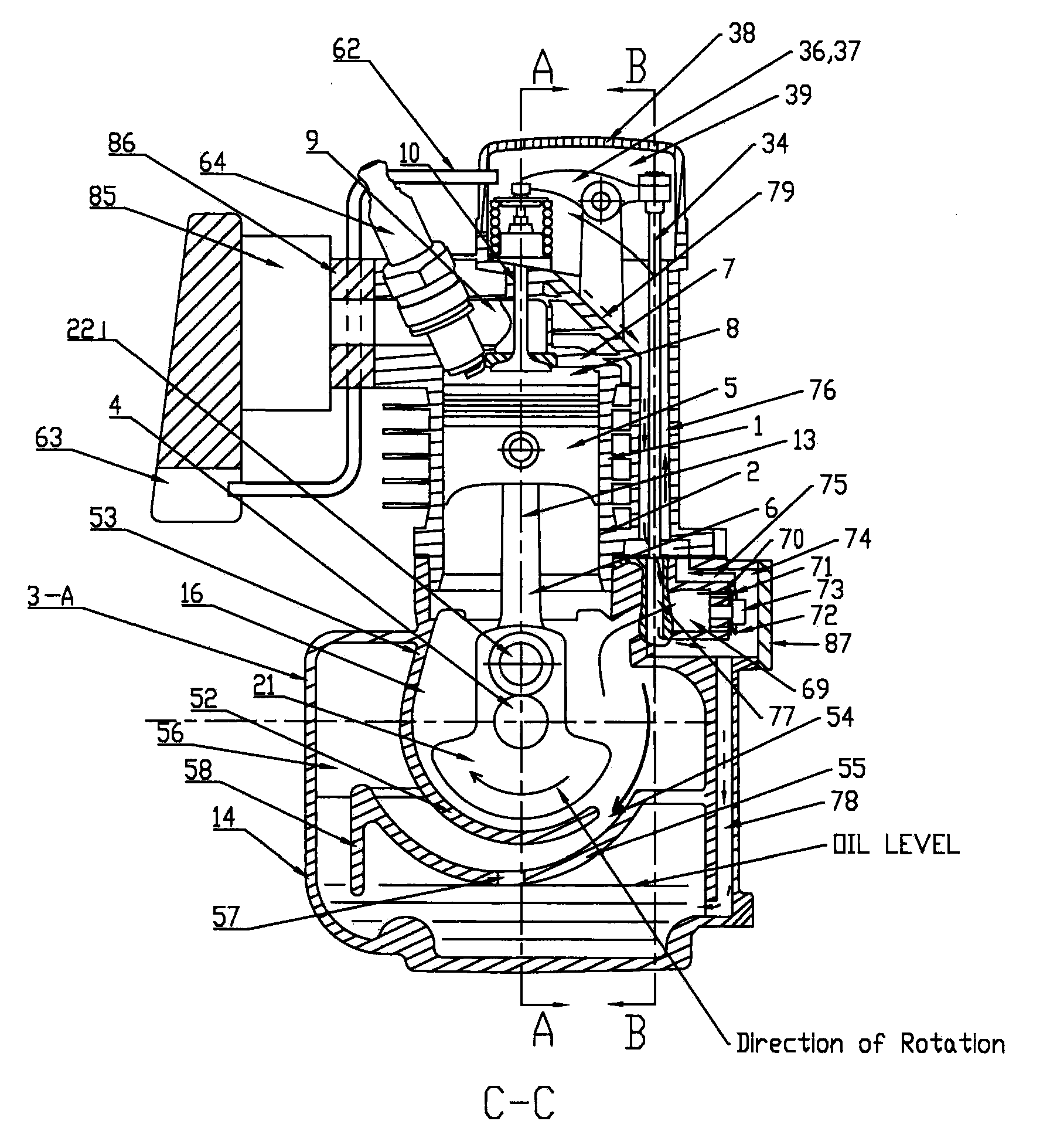
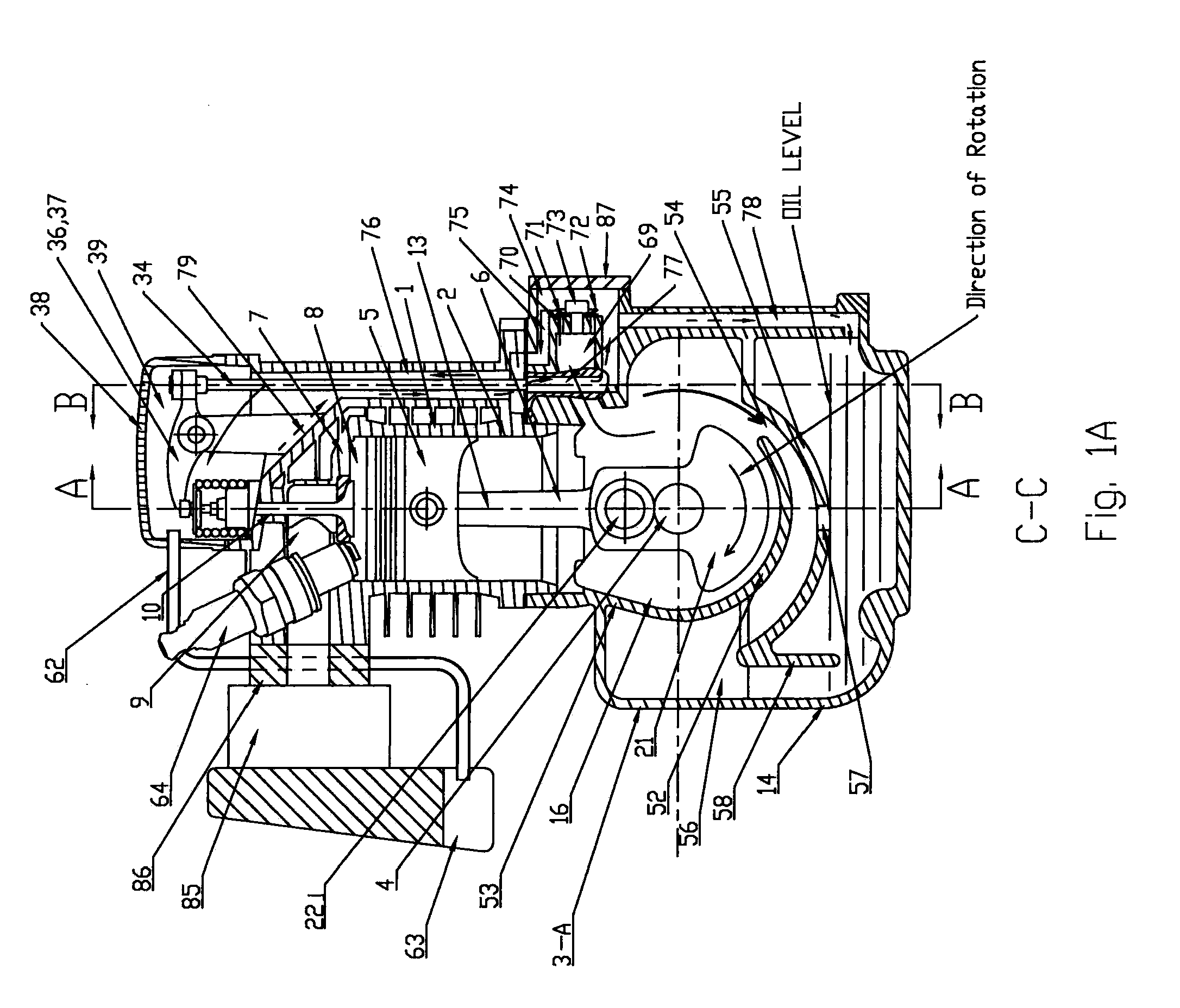
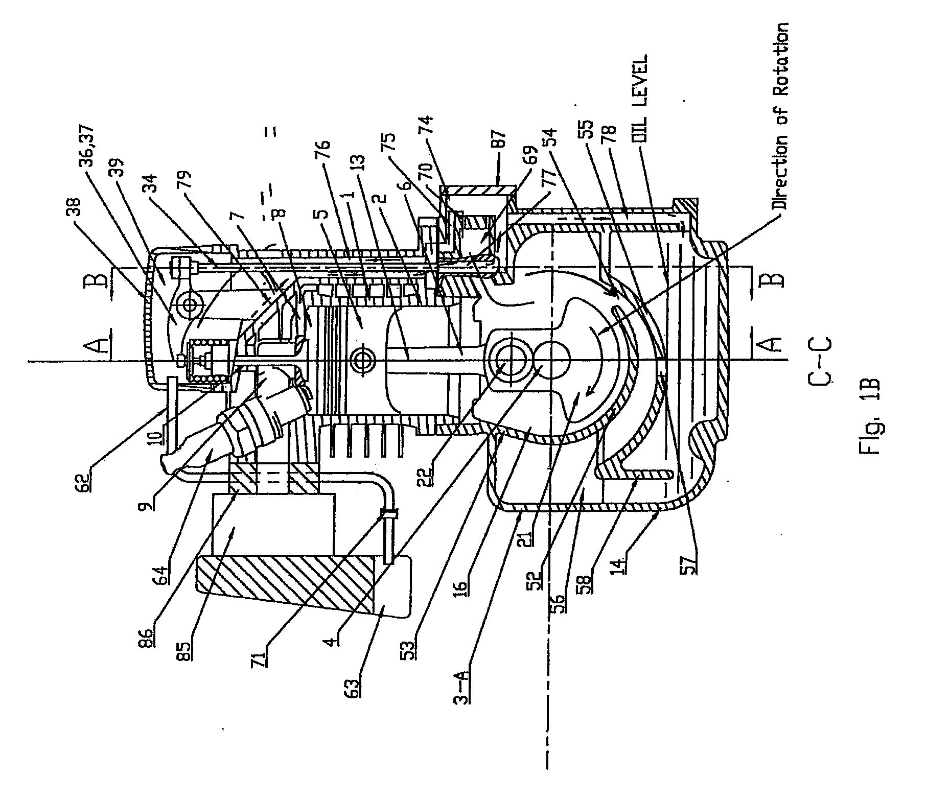
[0023]FIG. 1A and FIG. 2 illustrate a cross-sectional side elevation view of a four-cycle engine. The four-cycle engine is made of a lightweight aluminum housing including a cylinder block 1 having a cylindrical bore 2 formed therein and crankcases 3-A and 3-B.

[0024]A crankshaft 4 is pivotably mounted within the crankcases 3-A AND 3-B in a conventional manner.

[0025]A piston 5 slides within the cylindrical bore 2 and is connected to the crankshaft by a connecting rod 6.

[0026]A cylinder head 7 is affixed to the cylinder block 1 to define an enclosed combustion chamber 8.

[0027]The cylinder head 7 is provided with an intake port 9 selectively connected to the combustion chamber 8 by an intake valve 10.

[0028]The cylinder head 7 is also provided with an exhaust port 11 selectively connected to the combustion chamber 8 by an exhaust valve 12.

[0029]As illustrated in FIGS. 1A and 2, the cylinder axis 13 of four-cycle engine is generally upright when in normal use.

[0030]The crankcases 3-A and...


PUM


Abstract

An engine lubrication method is provided. The four-cycle engine has a lightweight aluminum alloy engine block having a cylindrical bore and an enclosed oil reservoir formed therein. A crankshaft is rotatably mounted in the engine block for rotation about a crankshaft axis. A piston reciprocates within the bore and is connected to the crankshaft by a connecting rod. A cam shaft is rotatably mounted in the crank shaft chamber for rotation about a cam shaft axis, parallel to the crank shaft axis. An oil pump driven by the cam shaft, which mates by cam gear with crank gear that is driven by crank shaft, inhales the oil from the oil reservoir to splash lubricate into the crank shaft chamber. The engine is provided with a cylinder head assembly defining a compact combustion chamber having a pair of overhead intake and exhaust ports and cooperating intake and exhaust valves. A lightweight, high-powered engine is thereby provided having relatively low HC and CO emissions. A circular arc wall surrounds around web of the crankshaft with a slight distance from the web. A scroll-shaped wall has gradually increased distance from said wall to the direction of rotation of the web and has partial overlap with the circular arc wall. The check valve splashes breathing mist oil from crank shaft room to breather room and causes the oil to supply to lubricate engine parts in valve chamber and the oil, after lubricating the parts, is returned into the oil reservoir.
The oil in crank shaft chamber, after lubricating engine parts, is returned to oil reservoir guided by scroll-shaped wall and a hole provided on the scroll-shaped wall.
In case of stock of engine oriented power take off side up or down, oil is prevented to flow from oil reservoir to combustion chamber by a weir which is provided between circular wall and scrolled or extended wall.

Description

BACKGROUND OF THE INVENTION[0001]1. Cross-Reference of Related Applications[0002]This application is a continuation-in-part application of U.S. patent application Ser. No. 11 / 903,003 by Kurihara et al., which is a continuation-in-part application of U.S. patent application Ser. No. 11 / 498,608 by Kurihara, now issued as U.S. Pat. No. 7,287,508, both of which are incorporated herein by reference.[0003]2. Field of the Invention[0004]This invention relates to an engine, and more particularly, an engine lubrication method for a small four-cycle internal combustion engine which is particularly suitable for use with portable or transportable power tools.[0005]3. Description of the Related Art[0006]Portable power tools, such as line trimmers, blower / vacuums, and chain saws, are mostly powered by two-cycle internal combustion engines or electric motors. Some transportable power tools, such as tiller / cultivators and generators, are currently powered by two-cycle or four-cycle internal combust...

Claims


Application Information

Patent Timeline
IPC IPC(8): F01M11/03F01M1/04
CPCF01M1/04F01M9/06F02B63/02F01M2001/126F01M2001/0261
Inventor KURIHARA, KATSUMIYAMAMOTO, SHIGEOGUO, BIN
Owner ETG
Why Eureka
Try Eureka