

H2-O2-H2O fuel generator
- Summary
- Abstract
- Description
- Claims
- Application Information
AI Technical Summary
Benefits of technology
Problems solved by technology
Method used
Image

Examples
Embodiment Construction
—OPERATION
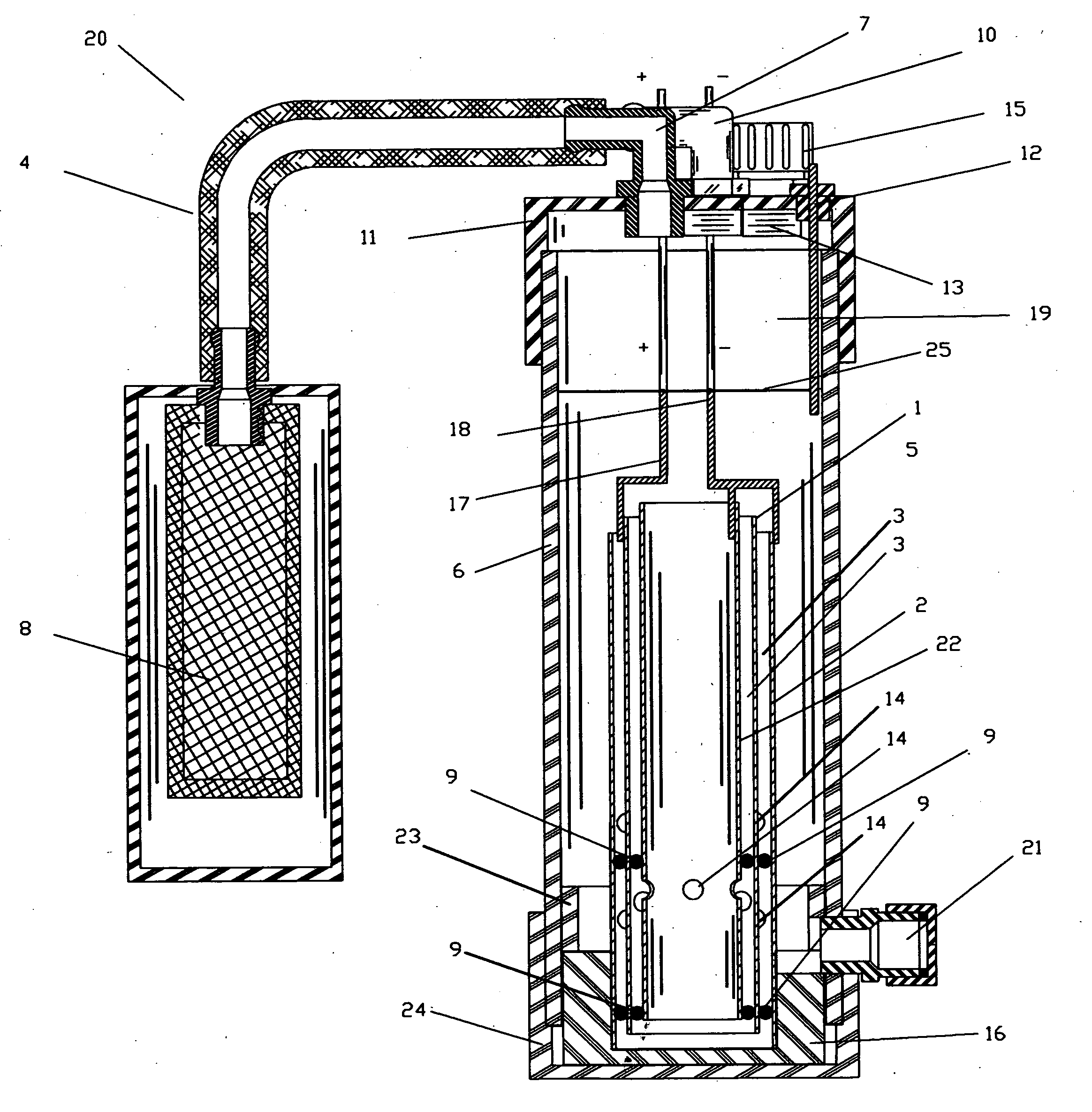
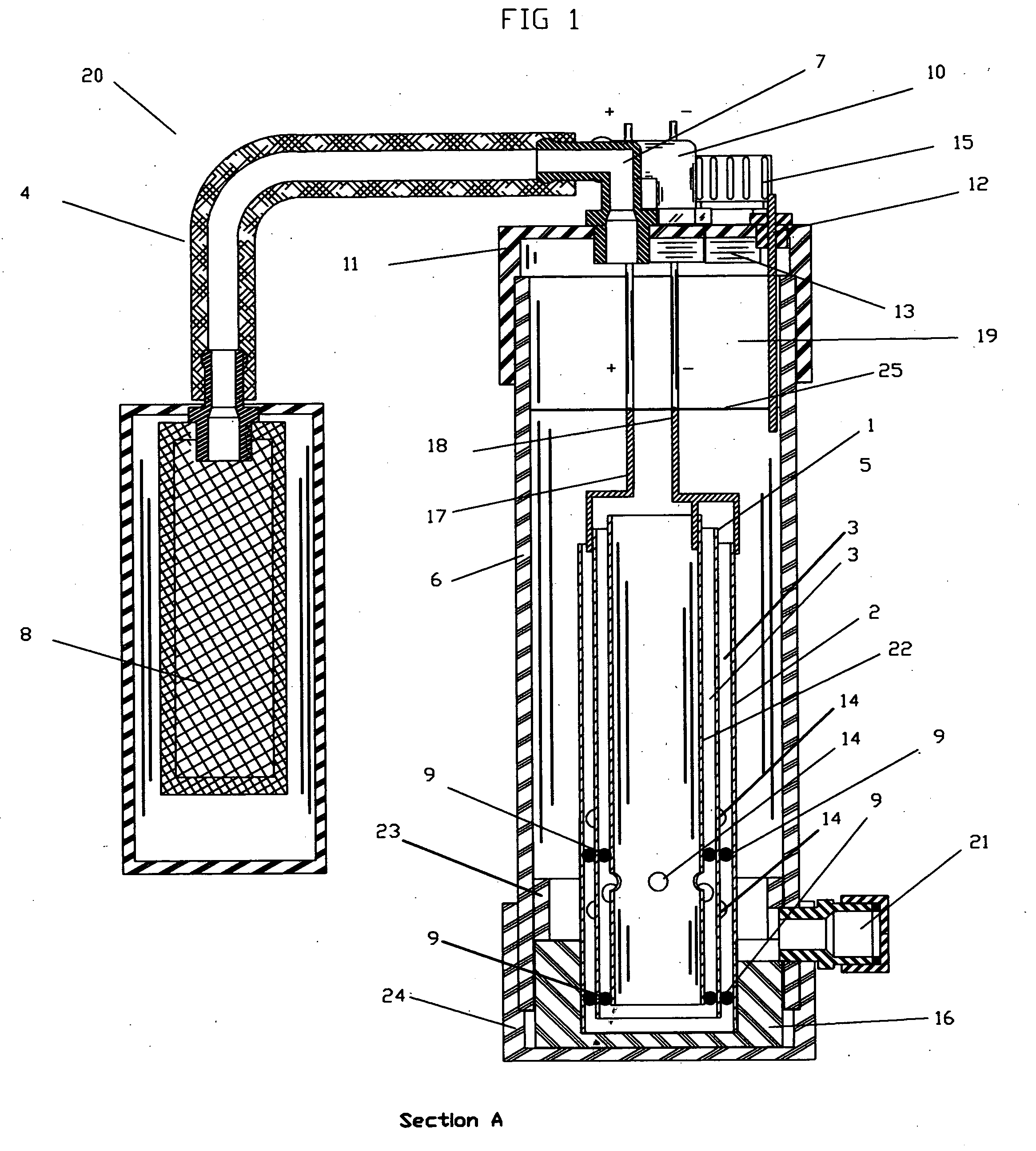
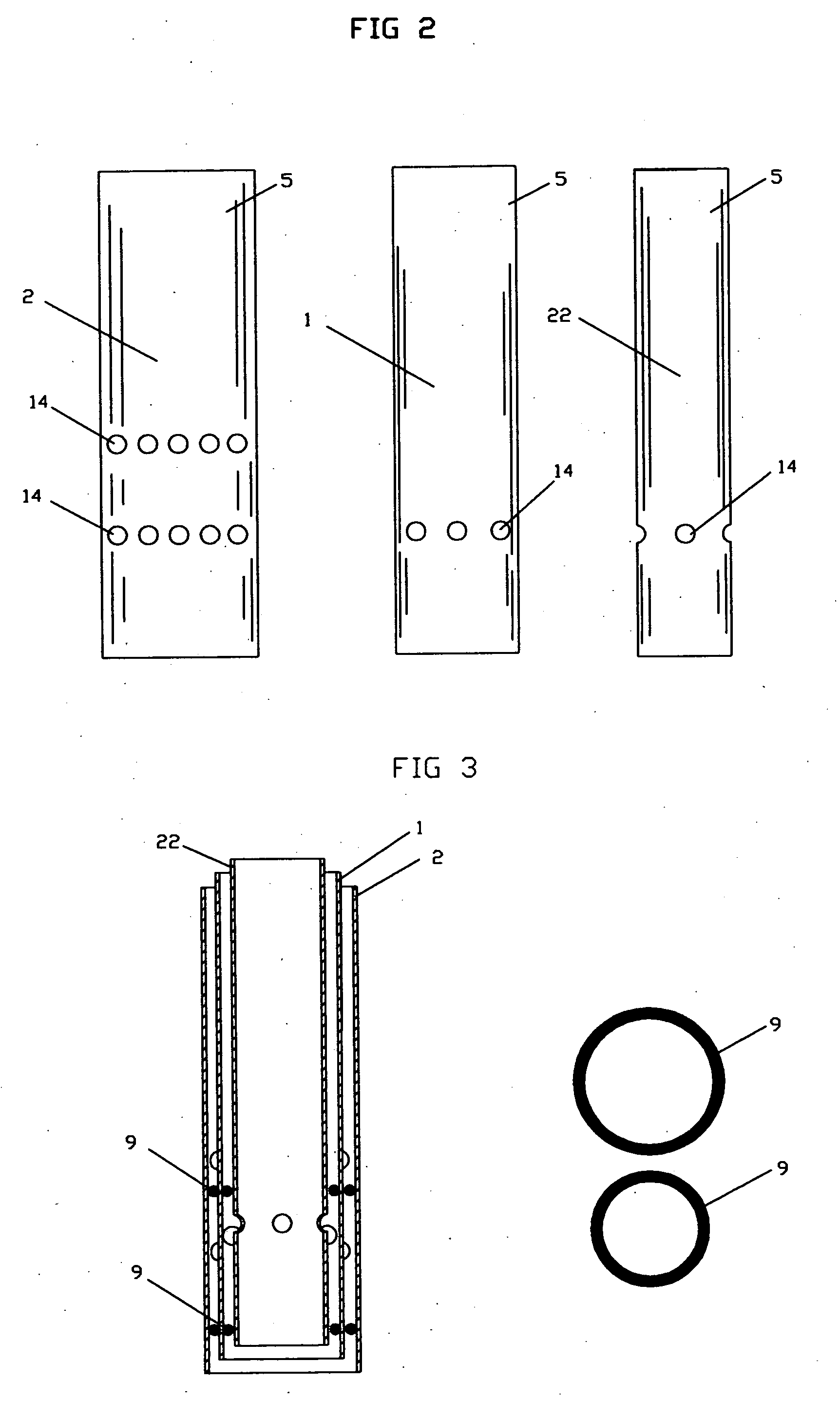
[0003]The invention is an electrolytic hydrogen, Oxygen, producing generator #20, which utilizes three cylindrical elements, FIG. 3 the anode element cylinder #1, cathode elements cylinder #2, and #22 and are arranged, in close proximity one within the other. The anodes have a positive charge that is delivered by anodes connecting wire and jumper #18, and the cathode that is placed in between the cathodes has an negative charge which delivered by cathode connecting wire #17. When the mineral drinking water is added to the generator through water fill cap and fitting #13 to the recommended fluid level the water level sensor #12 indicates full by the LED light FIG. 10 #3. At this point the electrolytic process of hydrogen ions and oxygen ions separate and travel to their opposite charges which is hydrogen at the negative plate the cathode element cylinder #1. The oxygen ions travel to the anodes surrounding the cathode, which is the positive outer anode cylinder 2 and inner ...
PUM
| Property | Measurement | Unit |
|---|---|---|
| Volume | aaaaa | aaaaa |
| Efficiency | aaaaa | aaaaa |
| Distance | aaaaa | aaaaa |
Abstract
Description
Claims
Application Information