Preheating using a laser beam

a laser beam and work piece technology, applied in the direction of arc welding apparatus, 3d object support structure, metal-working apparatus, etc., can solve the problems of cracks at or near the substrate, parts that are unsuitable for intended use, and difficult manufacturing, etc., to achieve the effect of a larger cross-sectional area

Inactive Publication Date: 2009-11-19
GENERAL ELECTRIC CO
View PDF6 Cites 58 Cited by
  • Summary
  • Abstract
  • Description
  • Claims
  • Application Information

AI Technical Summary

Benefits of technology

[0006]In an exemplary embodiment of the present invention, a laser deposition apparatus comprises a laser beam emitting system which emits a deposition laser beam to deposit a material on a work piece and a second laser beam to control a temperature of at least a portion of the work piece. The second laser beam has a larger cross-sectional area at the work piece than the deposition laser beam at the work piece.

Problems solved by technology

However, although these superalloys can tolerate the intense operational environment of an aircraft engine, they are very difficult to manufacture.
However, with some superalloys the process of LNSM results in cracks being formed at or near the substrate, at the interface point of layers and within the part being built.
These cracks result in the part being unsuitable for its intended use.
However, these methods are costly as they require additional expensive equipment and specialized work environments, as well as exposing the personnel performing the manufacturing to very high temperature work environments.

Method used


Image

  • Preheating using a laser beam
  • Preheating using a laser beam
  • Preheating using a laser beam

Examples


Embodiment Construction

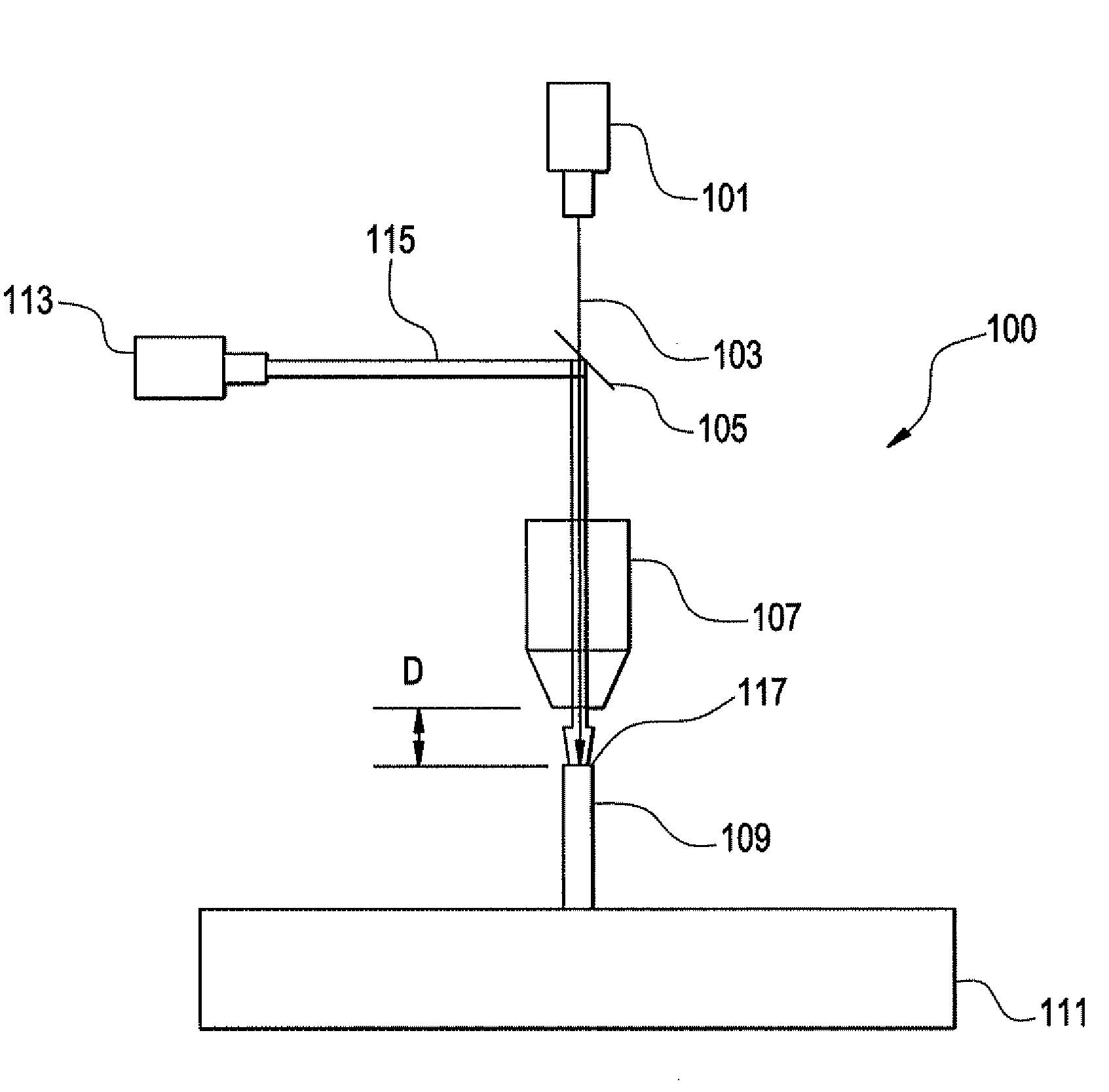
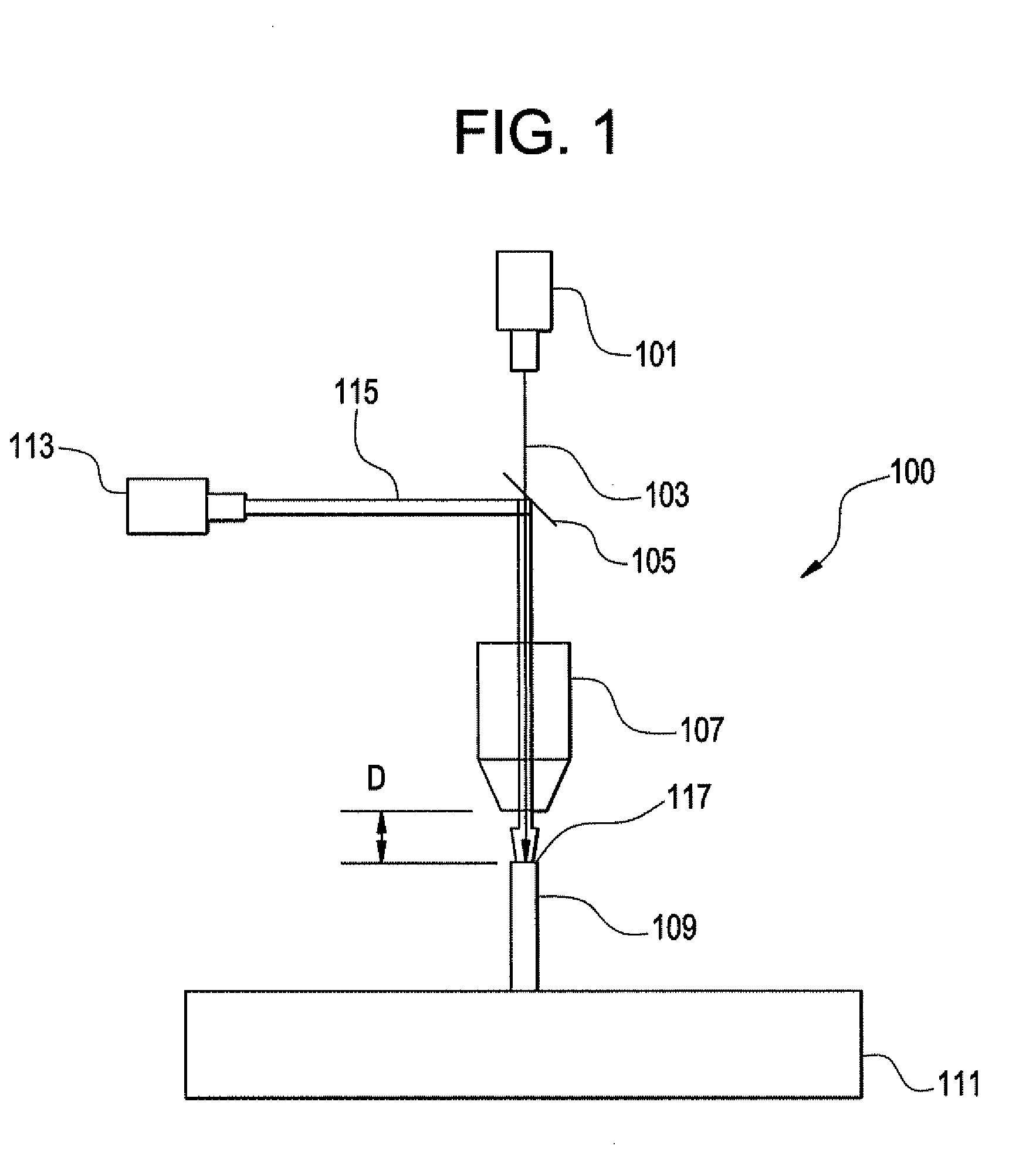
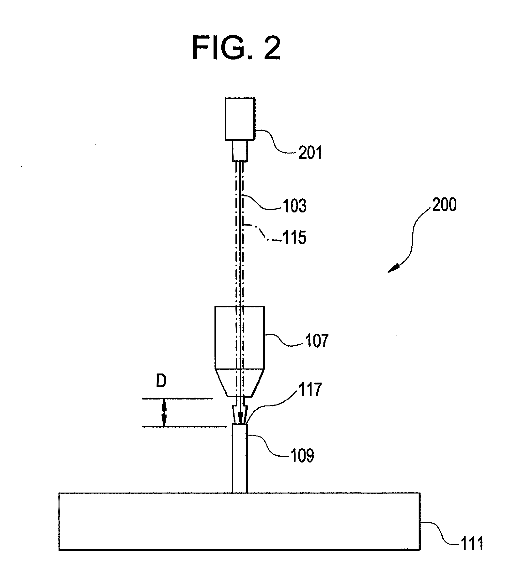
[0013]The present invention will be explained in further detail by making reference to the accompanying drawings, which do not limit the scope of the invention in any way.

[0014]FIGS. 1 and 2 depict diagrammatical representations of exemplary embodiments of the present invention. As shown in FIG. 1 the deposition system 100 contains both a deposition laser 101 and a heating laser 113. FIG. 2 depicts a system 200 where a single laser source 201 is employed to provide both the deposition laser and heating laser, as discussed more fully below. No importance is to be derived from the order in which the exemplary embodiments are discussed or exhibited in the figures.

[0015]It is further noted that the following discussion generally refers to a “heating laser” as being different from a “deposition laser.” However, the designation as a “heating laser” is not intended to be overly limiting as to require “heating.” It is contemplated that in various embodiments of the present invention, the “h...


PUM

PropertyMeasurementUnit
sizeaaaaaaaaaa
temperatureaaaaaaaaaa
areaaaaaaaaaaa

Abstract

A laser deposition apparatus is provided which uses a laser beam to manufacture and/or repair a work piece by depositing a material on a work piece and controlling a temperature of the work piece using a laser beam prior to, during and/or after deposition. The temperature controlling laser beam has a larger cross-sectional area than a laser beam used for deposition at the surface of the work piece.

Description

BACKGROUND OF THE INVENTION[0001]This invention relates to preheating a work piece with a laser beam and more specifically to preheating a work piece with a laser beam during a laser manufacturing procedure.[0002]Because of the high heat and stresses experienced in the operation of modern day aircraft engines, and the like, engine components are often made from superalloys, such as nickel or cobalt or iron based superalloys. However, although these superalloys can tolerate the intense operational environment of an aircraft engine, they are very difficult to manufacture.[0003]A known method of manufacturing and repairing such components is referred to as Laser Net Shape Manufacturing (LNSM). During LNSM a laser is used to heat and liquefy granules of a material to be deposited (i.e., super alloy granules). The liquefied material is then directed to and deposited on a substrate and built up in repeated passes until the part is completed. One advantage of LNSM over traditional casting ...

Claims


Application Information

Patent Timeline
Patent Type & Authority Applications(United States)
IPC IPC(8): B23K26/34
CPCB22F3/1055B22F2998/00B23K26/0604B23K26/34B22F2003/1056B23K35/0244B23K26/3206B23K26/3213B23P6/00B22F3/003B23K26/32B33Y10/00B33Y30/00B29C64/153B23K2103/02B23K2103/26B23K2103/50B29C64/268B29C64/295Y02P10/25B22F10/25B22F12/90B22F12/53B22F12/45
Inventor ERIKSON, CARL EDWARDSCHOONOVER, JEFFREY JON
Owner GENERAL ELECTRIC CO
Why Eureka
Try Eureka