
Side-view light emitting diode

Inactive Publication Date: 2009-11-19
HON HAI PRECISION IND CO LTD
View PDF1 Cites 12 Cited by
  • Summary
  • Abstract
  • Description
  • Claims
  • Application Information

AI Technical Summary

Benefits of technology

[0006]For obtaining the side-view LED which emits most of light from a lateral side thereof, the LED chip is lain down. Thus, a main part of the light emitted by the LED chip can directly shoot towards the lateral side of the housing and leaves the housing from the lateral side. However, the other part of the light emitted by the LED chip shoots towards a top surface of the capsulation material, which induces some light to leave the side-view LED from the top surface of the capsulation material and decreases the extracting rate of the light from the lateral side of the side-view LED.
[0006]For obtaining the side-view LED which emits most of light from a lateral side thereof, the LED chip is lain down. Thus, a main part of the light emitted by the LED chip can directly shoot towards the lateral side of the housing and leaves the housing from the lateral side. However, the other part of the light emitted by the LED chip shoots towards a top surface of the capsulation material, which induces some light to leave the side-view LED from the top surface of the capsulation material and decreases the extracting rate of the light from the lateral side of the side-view LED.

Problems solved by technology

However, the other part of the light emitted by the LED chip shoots towards a top surface of the capsulation material, which induces some light to leave the side-view LED from the top surface of the capsulation material and decreases the extracting rate of the light from the lateral side of the side-view LED.

Method used


Image

  • Side-view light emitting diode
  • Side-view light emitting diode
  • Side-view light emitting diode

Examples


Embodiment Construction

[0014]Reference will now be made to the drawings to describe the various present embodiments in detail.

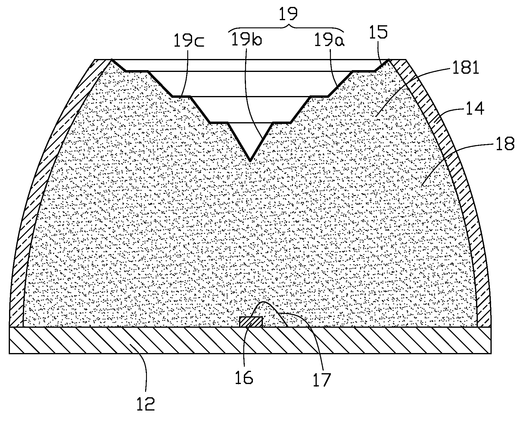
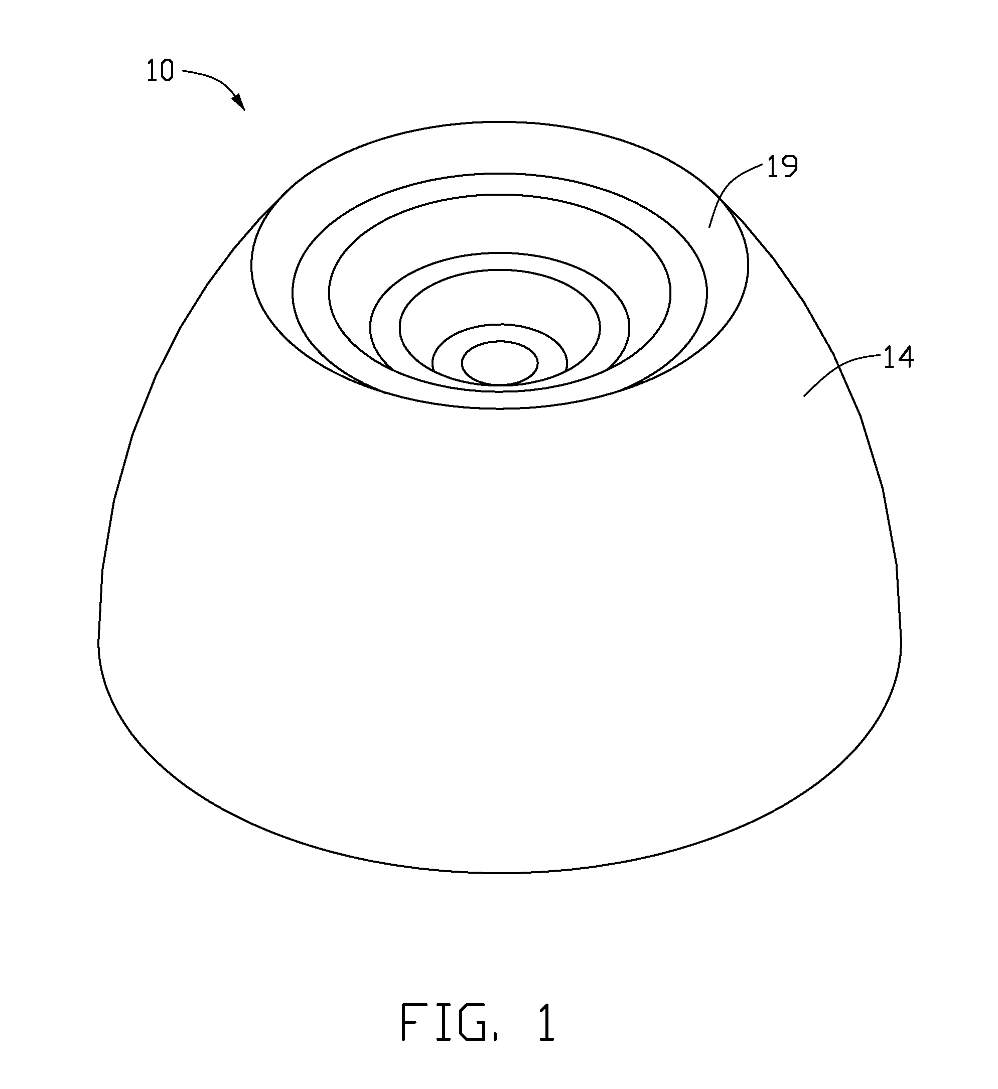
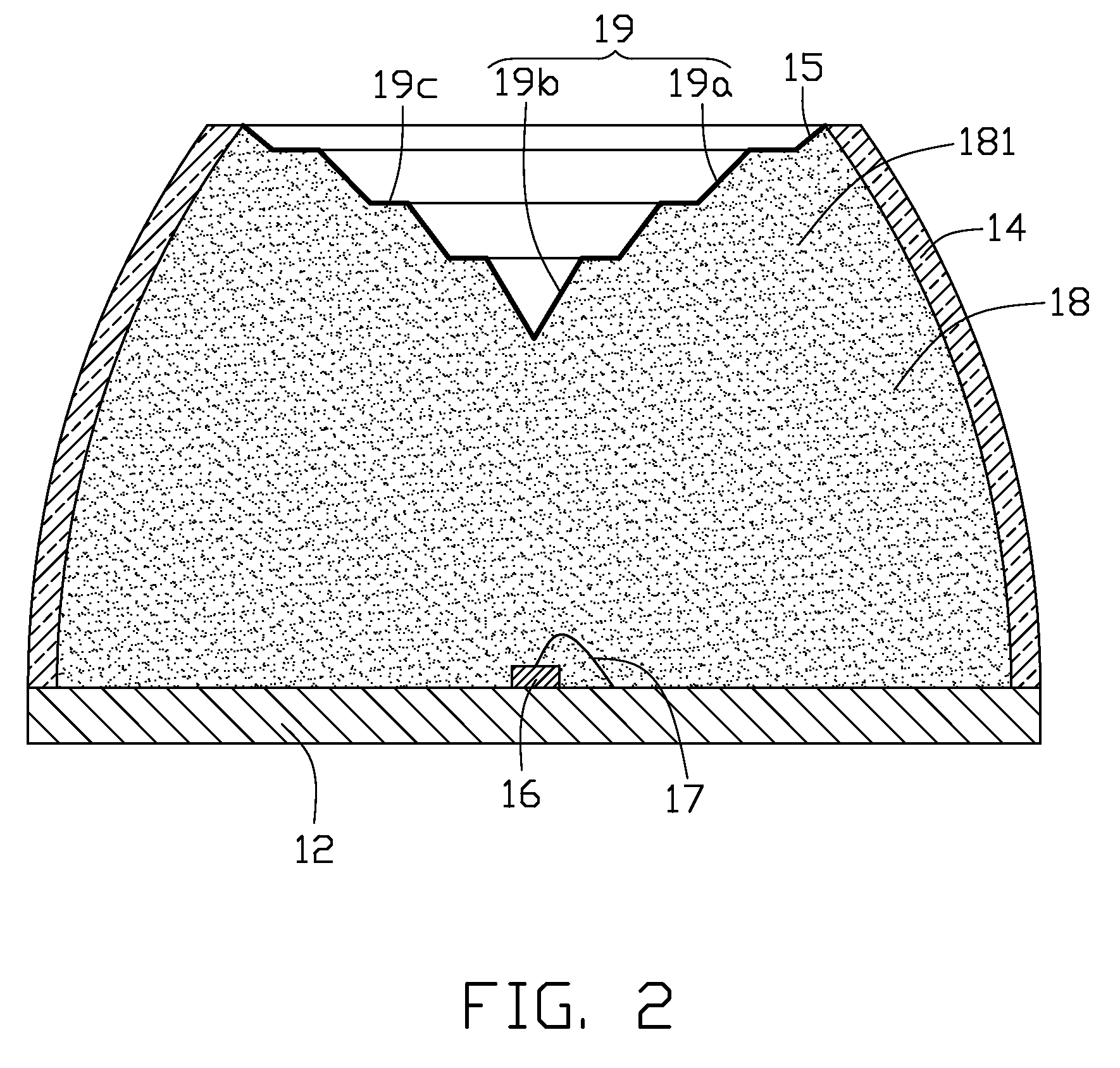
[0015]Referring to FIGS. 1-2, a side-view light emitting diode (LED) 10 according to a first exemplary embodiment of the present invention includes a substrate 12, a housing 14, a reflecting layer 15, a LED chip 16 and a capsulation material 18.

[0016]The substrate 12 is made of materials having electric and thermal conductivities. In this embodiment, the substrate 12 is made of metal such as aluminum, or copper. Alternatively, the substrate 12 can be made of ceramic.

[0017]The housing 14 is made of transparent, light permeable materials, such as epoxy resin, glass, etc. A horizontal section of the housing 14 has an annular shape, and a vertical section of the housing 14 is substantially a frustum with top and bottom ends of the housing 14 being open. A lateral side of the housing 14 is arc shaped. A diameter of the housing 14 gradually decreases from the bottom end toward the top en...


PUM


Abstract

An exemplary side-view light emitting diode (LED) includes a substrate, a housing, a LED chip, a capsulation material and a reflecting layer. The housing and the substrate cooperatively form a receiving space therebetween. The LED chip is received in the receiving space and electrically connected with the substrate. The capsulation material is filled in the receiving space and encapsulates the LED chip in the housing. An indent is defined in a top portion of the capsulation material to cave a top surface of the capsulation material. The reflecting layer is spread on the top surface of the capsulation material. The light emitted from the LED chip upwardly towards the top surface of the capsulation material is reflected to a lateral side of the housing by the reflecting layer. The indent has a horizontal section with a size decreased along a top-to-bottom direction. The housing has a diameter gradually increased along the top-to-bottom direction.

Description

BACKGROUND [0001]1. Technical Field[0002]The present invention relates to light emitting diodes, and particularly to a side-view light emitting diode.[0003]2. Description of Related Art[0004]Presently, LEDs (light emitting diodes) are preferred to be used in the non-emissive display devices instead of CCFLs (cold cathode fluorescent lamp) due to the high brightness, long life-span, and wide color gamut of the LEDs.[0005]A related side-view light emitting diode (LED) includes a substrate, a housing disposed on the substrate, a LED chip disposed on the substrate and in the housing, an electrode located on the substrate, a gold wire electrically connecting the LED chip with the electrode, and a capsulation material filled in the housing for encapsulating the LED chip, the electrode and the gold wire in the housing.[0006]For obtaining the side-view LED which emits most of light from a lateral side thereof, the LED chip is lain down. Thus, a main part of the light emitted by the LED chip...

Claims


Application Information

Patent Timeline
IPC IPC(8): H01L33/00H01L33/54H01L33/60
CPCH01L33/54H01L33/60H01L2224/48091H01L2224/45144H01L2924/00014H01L2924/00
Inventor CHANG, CHIA-SHOU
Owner HON HAI PRECISION IND CO LTD
Learn More