Vibrating Element

Inactive Publication Date: 2009-11-19
FUNAI ELECTRIC CO LTD
View PDF2 Cites 15 Cited by
  • Summary
  • Abstract
  • Description
  • Claims
  • Application Information

AI Technical Summary

Benefits of technology

[0015]The present invention has been proposed in order to solve the aforementioned problems, and an object of the present invention is to provide a vibrating elem

Problems solved by technology

Therefore, the structure of the electromagnetic actuator is disadvantageously complicated.
In the vibrating mirror scanner driving circuit described in the aforementioned Japanese Patent No. 3806826, the voltage sampler can detect the counter electromotive voltage only in the period where the excitation pulse voltage is not applied in each half cycle of the vibrating mirror driven at the resonance frequency, and hence a detectable period for the vibrational state of the vibrating mirror is conceivably disadvantageously short.
In the planar galvanomirror driving circuit described in the aforementioned Japanese Patent Laying-Open No. 2002-277809, the counter electromotive force waveform can be acquired only in the second half of the waveform detected by the counter electromotive force detecting portion (second half of the resonantly driven vibration), and hence a detectable period for t

Method used


Image

  • Vibrating Element
  • Vibrating Element
  • Vibrating Element

Examples


Embodiment Construction

[0046]An embodiment of the present invention is now described with reference to the drawings.

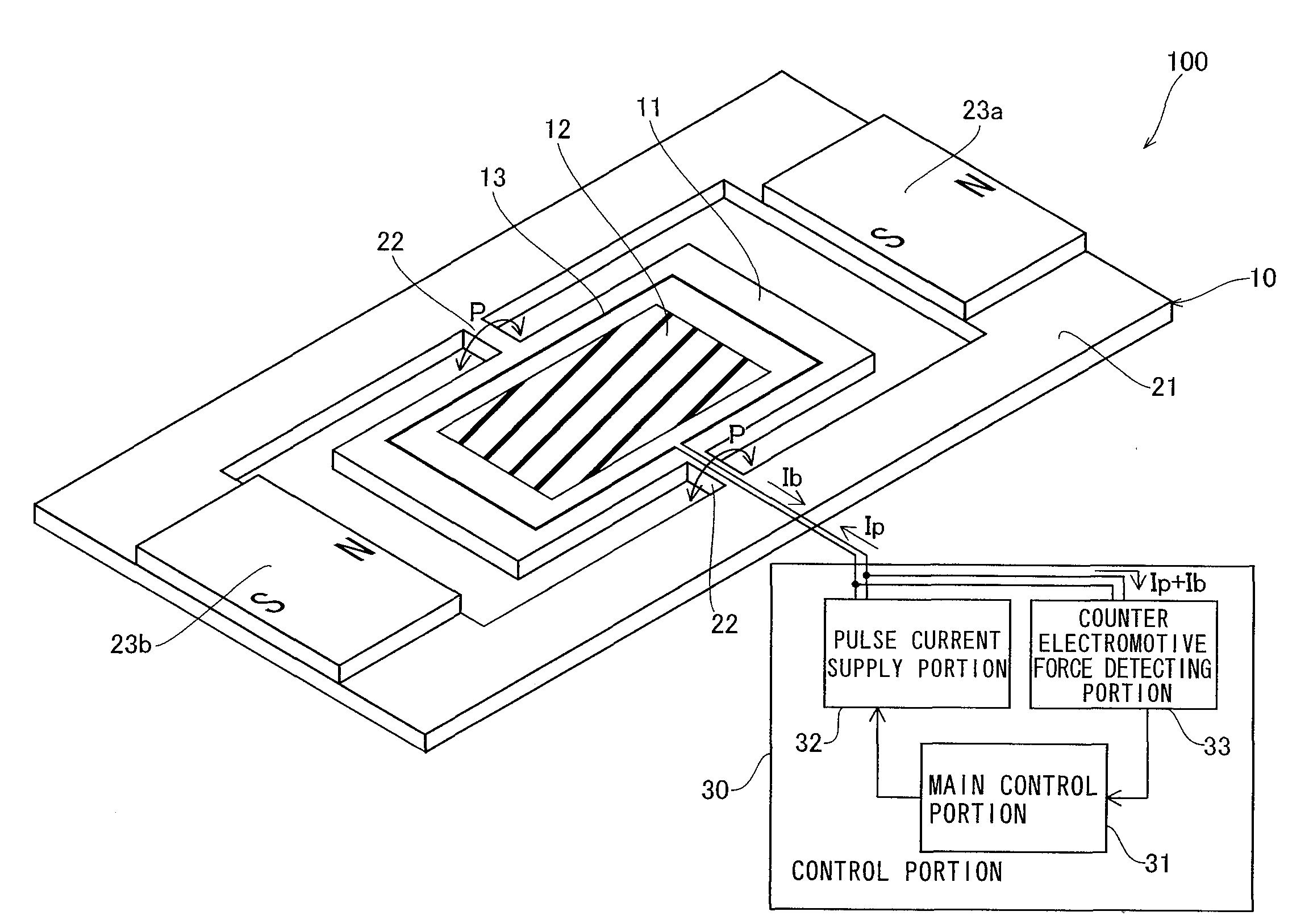
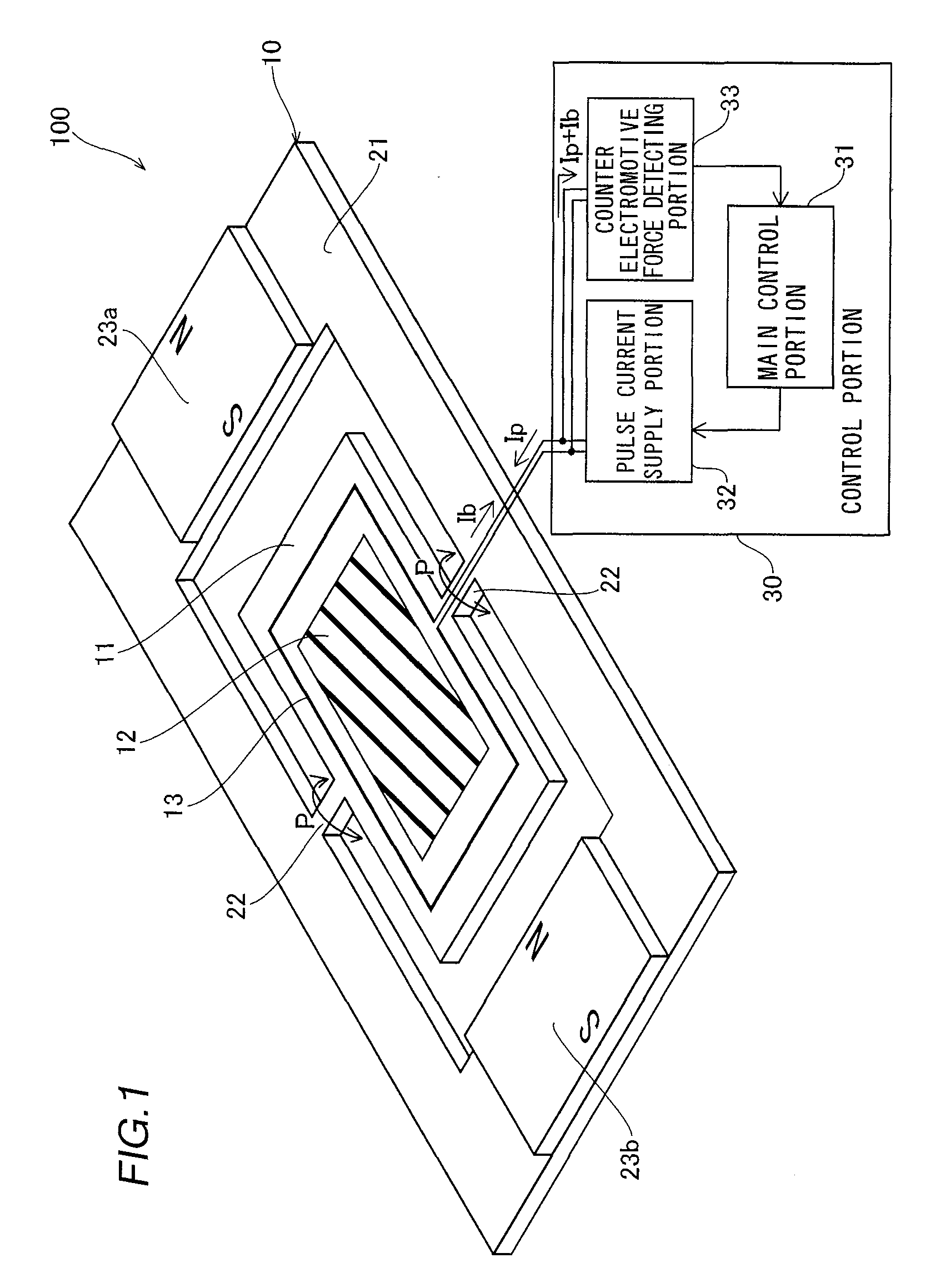
[0047]First, the structure of an electromagnetically driven mirror 100 according to the embodiment of the present invention is described with reference to FIGS. 1 to 4. According to this embodiment, the present invention is applied to the electromagnetically driven mirror 100 employed as an exemplary vibrating element.

[0048]As shown in FIG. 1, the electromagnetically driven mirror 100 according to the embodiment of the present invention is constituted of a mirror body portion 10 and a control portion 30.

[0049]The mirror body portion 100 of the electromagnetically driven mirror 100 is constituted of a movable portion 11 having a mirror 12 mounted on the central portion thereof and a fixed portion 21 rotatably supporting the movable portion 11 through a pair of rotating shafts 22, as shown in FIG. 1. The movable portion 11, the rotating shafts 22 and the fixed portion 21 are integrally formed....


PUM


Abstract

This vibrating element includes a movable portion driven to vibrate at a prescribed resonance frequency, a driving portion vibrating the movable portion by cyclically supplying a pulse signal and a detecting portion detecting the vibrational state of the movable portion, while the driving portion is so formed as to supply the pulse signal at a first frequency substantially identical to the resonance frequency of the movable portion at least in starting and to cyclically supply the pulse signal at a second frequency smaller than the first frequency in detection of the vibrational state of the movable portion.

Description

BACKGROUND OF THE INVENTION[0001]1. Field of the Invention[0002]The present invention relates to a vibrating element, and more particularly, it relates to a vibrating element including a movable portion driven to vibrate at a prescribed resonance frequency.[0003]2. Description of the Background Art[0004]A vibrating element including a movable portion driven to vibrate at a prescribed resonance frequency is known in general, as disclosed in each of Japanese Patent Laying-Open No. 2004-242488, Japanese Patent No. 3806826, Japanese Patent Laying-Open No. 2002-277809, Japanese Patent Laying-Open No. 2007-151244 and Japanese Patent Laying-Open No. 2001-305471, for example.[0005]The aforementioned Japanese Patent Laying-Open No. 2004-242488 discloses an electromagnetic actuator including a movable portion, first and second coils provided on the movable portion, a permanent magnet working a magnetic field on the first and second coils, two driving portions provided for the first and second...

Claims


Application Information

Patent Timeline
IPC IPC(8): H02K33/10H02K33/18H02P25/034H02P25/06
CPCG02B26/085H02P25/027H02K33/18H02P25/032
Inventor MATSUBARA, HIROKITAKEMOTO, SEIJIHIRAI, TOMOHISAMURAYAMA, MANABU
Owner FUNAI ELECTRIC CO LTD
Why Eureka
Try Eureka