Adaptive Compensation Scheme for LC Circuits In Feedback Loops

a linear integrated circuit and feedback loop technology, applied in the direction of dc-dc conversion, power conversion systems, instruments, etc., can solve the problems of limiting the gain loss that is capable of being achieved, affecting the output voltage, and affecting the operation of the circui

Inactive Publication Date: 2009-11-19
MICREL
View PDF5 Cites 123 Cited by
  • Summary
  • Abstract
  • Description
  • Claims
  • Application Information

AI Technical Summary

Benefits of technology

[0018]According to one embodiment of the present invention, a method for providing adaptive compensation for an electrical circuit where the electrical circuit includes an inductor-capacitor network connected in a feedback loop being compensated by a first compensation capacitance value and a second compensation capacitance value defining the frequency locations of two compensation zeros in the feedback loop and where the inductor-capacitor network includes a first inductor and a first capacitor includes: measuring the inductance value of the first inductor; when the

Problems solved by technology

However, poles and zeros on the right half plane of a complex frequency plane are usually problematic and difficult to manipulate and is not addressed in the present application.
That is, at some point, the dynamic resistance of the gain stage will limit the gain loss capable of being achieved by the capacitor.
If the feedback control loop is not compensated, the LC circuit alone contributes an −180° phase shift to the system and loop instability results, causing the output voltage to oscillate.
If the feedback control loop is not compensated, LC circuit 11 alone contributes an −180° phase shift to the system and loop instability results, causing the output voltage to oscillate.
When external compensation (off-chip) is used, it is often very difficult for users of the switching regulator to determine the optimal

Method used


Image

  • Adaptive Compensation Scheme for LC Circuits In Feedback Loops
  • Adaptive Compensation Scheme for LC Circuits In Feedback Loops
  • Adaptive Compensation Scheme for LC Circuits In Feedback Loops

Examples


Embodiment Construction

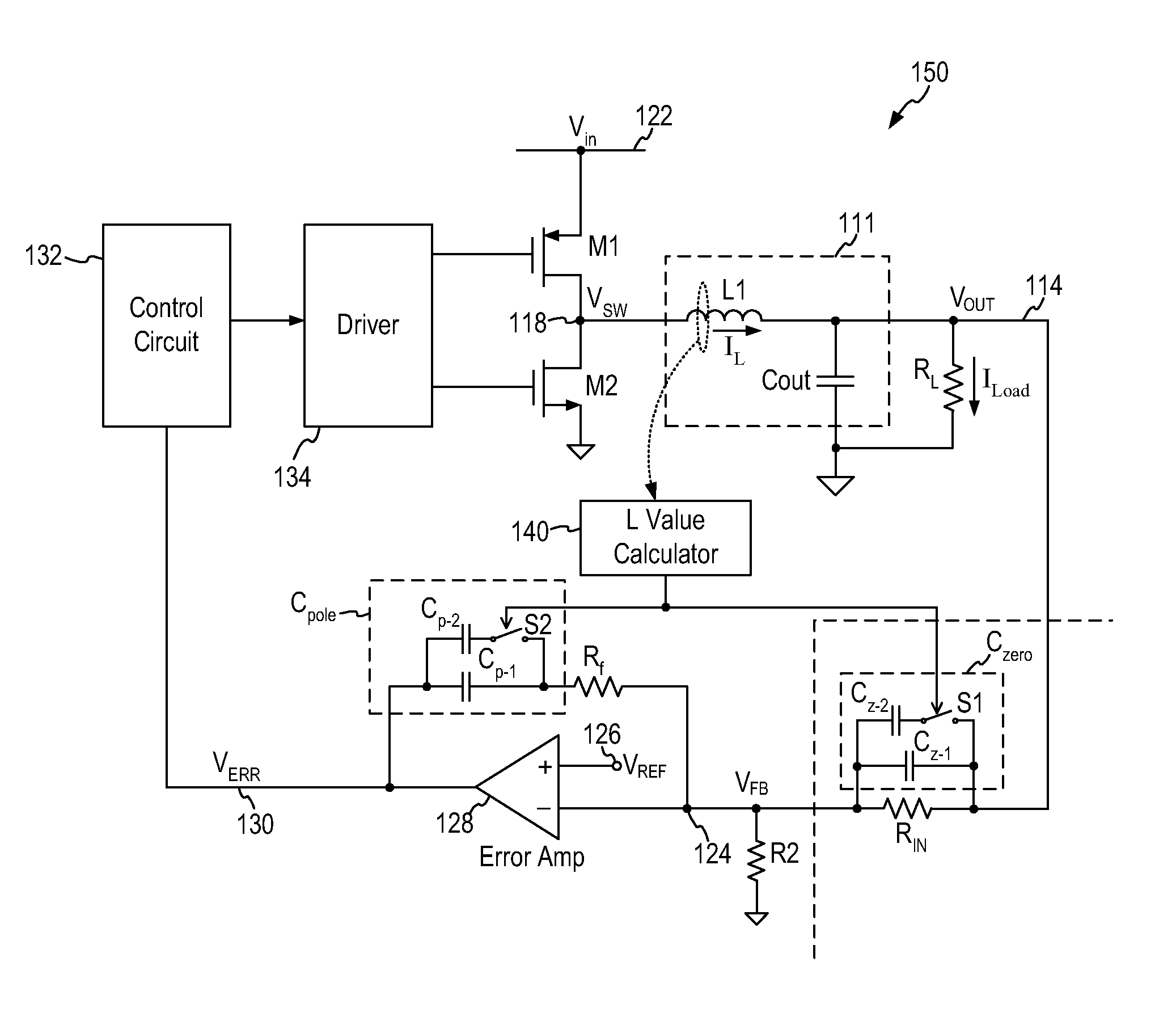
[0028]In accordance with the principles of the present invention, an electrical circuit including an inductor-capacitor (LC) filter circuit as a filter circuit connected in a feedback loop incorporates an adaptive compensation circuit providing compensation based on the inductance value of the LC circuit. More specifically, the adaptive compensation circuit senses the inductance value of the LC circuit and adjusts the compensation capacitance accordingly to provide effective pole cancellation and zero compensation for feedback loop stability.

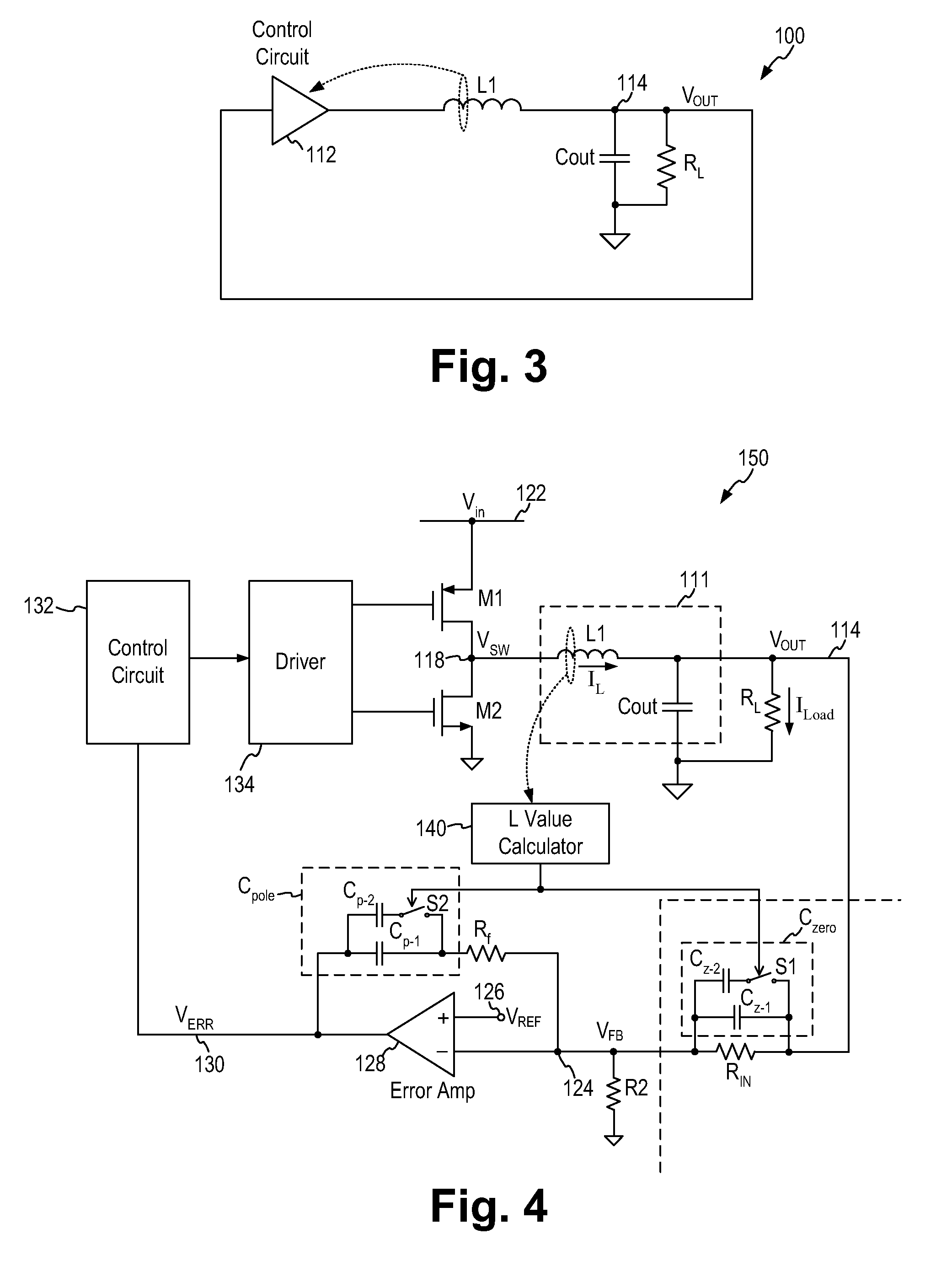
[0029]FIG. 3 is a representative circuit diagram of an electrical circuit including an LC circuit in a feedback loop and incorporating the adaptive compensation scheme according to one embodiment of the present invention. Referring to FIG. 3, an electrical circuit 100 includes an LC circuit (inductor L1 and capacitor Cout) for filtering the output signal from a control circuit 112. The output voltage VOUT is used to drive a load represented by l...


PUM


Abstract

A method for providing adaptive compensation for an electrical circuit where the electrical circuit includes an inductor-capacitor network connected in a feedback loop being compensated by a first compensation capacitance value and a second compensation capacitance value defining the frequency locations of two compensation zeros includes: measuring the inductance value of the inductor; when the inductance value is greater than a first threshold value, increasing the first and second compensation capacitance values so that the frequency locations of the two compensation zeros are adjusted for compensating the poles introduced by the first inductor and the first capacitor; and when the inductance value is less than the first threshold value, decreasing the first and second compensation capacitance values so that the frequency locations of the two compensation zeros are adjusted for compensating the poles introduced by the first inductor and the first capacitor.

Description

FIELD OF THE INVENTION[0001]The invention relates to a circuit and method for providing compensation to a linear integrated circuit, in particular, to a circuit and method for providing adaptive compensation for the LC circuit in a switching regulator.DESCRIPTION OF THE RELATED ART[0002]Closed loop negative feedback systems are commonly employed in linear integrated circuits. For instance, switching regulators use a feedback loop to monitor the output voltage in order to provide regulation. To ensure stability in any closed loop system, the Nyquist criterion must be met. The Nyquist criterion states that a closed loop system is stable if the phase shift around the loop is less than 180 degrees at unity gain. Typically, a compensation circuit is added to a feedback loop to modulate the phase shift of the feedback loop to obtain stability.[0003]The frequency response of a linear circuit can be characterized by the presence of “poles” and “zeros.” A “pole” is a mathematical term which ...

Claims


Application Information

Patent Timeline
IPC IPC(8): G05F1/652G05F1/10
CPCH02M3/156
Inventor WENG, MATTHEWVINN, CHARLES
Owner MICREL
Why Eureka
Try Eureka