
Dispersive antenna for RFID tags

a technology of rfid tags and dispersive antennas, applied in the field of transponders, can solve the problems of low sensitivity, low power output of batteryless rfid tags powered by scavenged rf power, and ineffective over longer ranges, and achieve the effect of improving dispersion

Active Publication Date: 2009-11-19
RADIOFIDO
View PDF28 Cites 40 Cited by
  • Summary
  • Abstract
  • Description
  • Claims
  • Application Information

AI Technical Summary

Benefits of technology

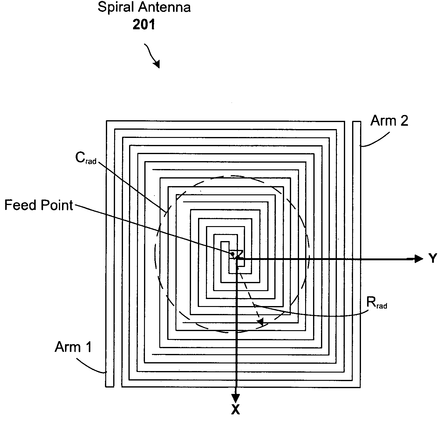
[0007]One embodiment of the present invention provides a transponder. The transponder includes a rectifier, a radio-frequency identification (RFID) circuit for receiving and responding to interrogation signals, and a frequency dispersion element for receiving a multi-phase input signal and creating a pulse therefrom for input to the rectifier. The transponder may further include a hysteretic switch coupled between the rectifier and the RFID circuit (or other suitable mechanism to operatively couple the rectifier to the RFID circuit). The frequency dispersion element may comprise, for example, at least one of an antenna, a surface acoustic wave (SAW) correlator, and a dispersive delay line. For instance, in some cases, the frequency dispersion element comprises a spiral antenna. In some such configurations, the spiral antenna comprises an Archimedean spiral antenna, or a log spiral antenna. In other cases, the frequency dispersion element comprises a spiral a...

Problems solved by technology

However, there are problems associated with passive configurations.
For instance, batteryless RFID tags powered by scavenged RF power exhibit a relatively low power output and low sensitivity, and therefore are ineffective over longer ranges.
As such, passive RFID tags are typically limited to applications having a short operation range (e.g., less than a few feet), such as those RFID tags used at point of sale for anti-shoplifting and inventory control.
In a more general sense, even RFID tags configured with on-board power sources are range limited to some extent.

Method used


Image

  • Dispersive antenna for RFID tags
  • Dispersive antenna for RFID tags
  • Dispersive antenna for RFID tags

Examples


Embodiment Construction

[0016]RFID tag designs and sensors are disclosed that include a dispersive antenna and exhibit greater detection ranges relative to conventional designs. The designs can be used to benefit both active and passive RFID tag configurations.

[0017]General Overview

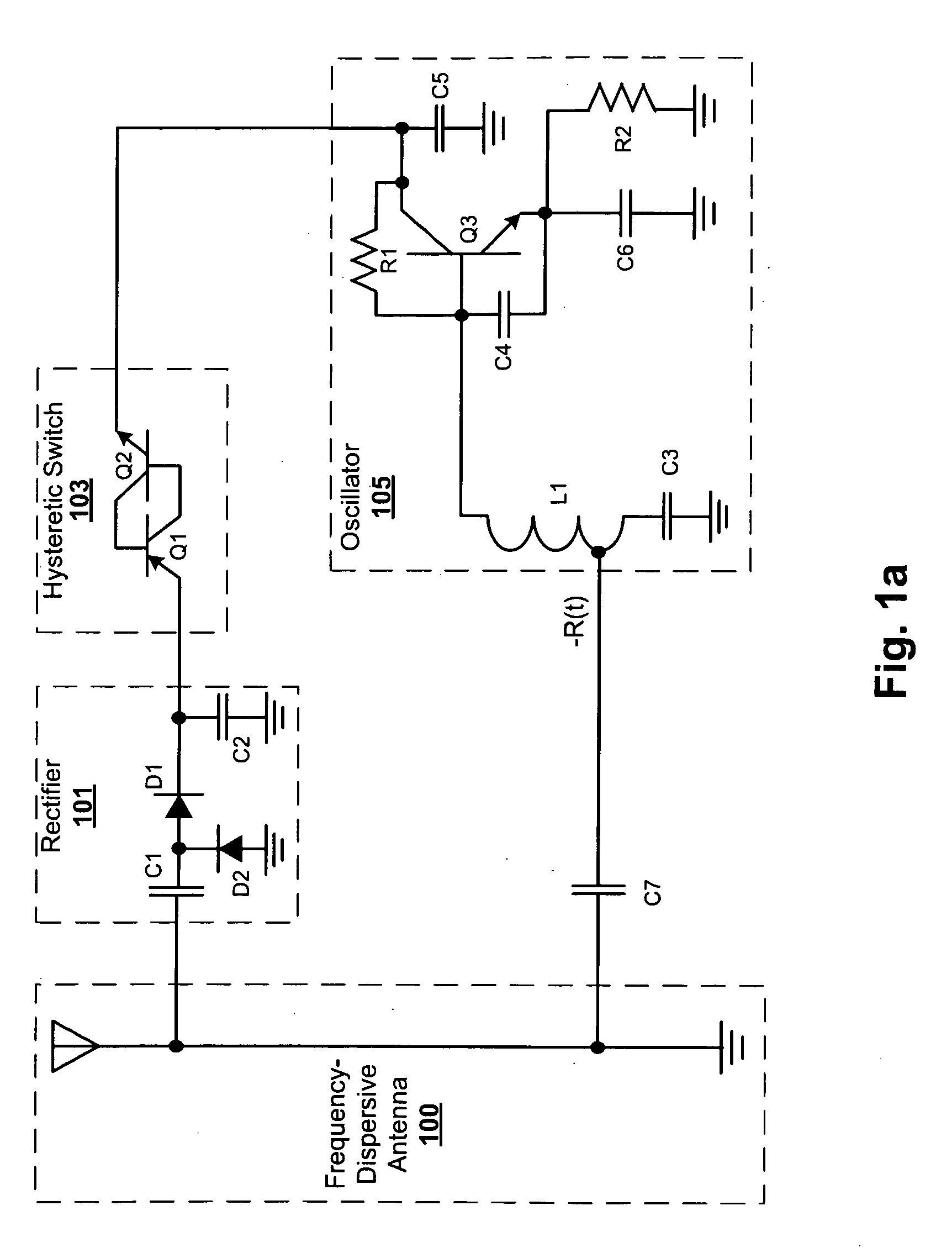
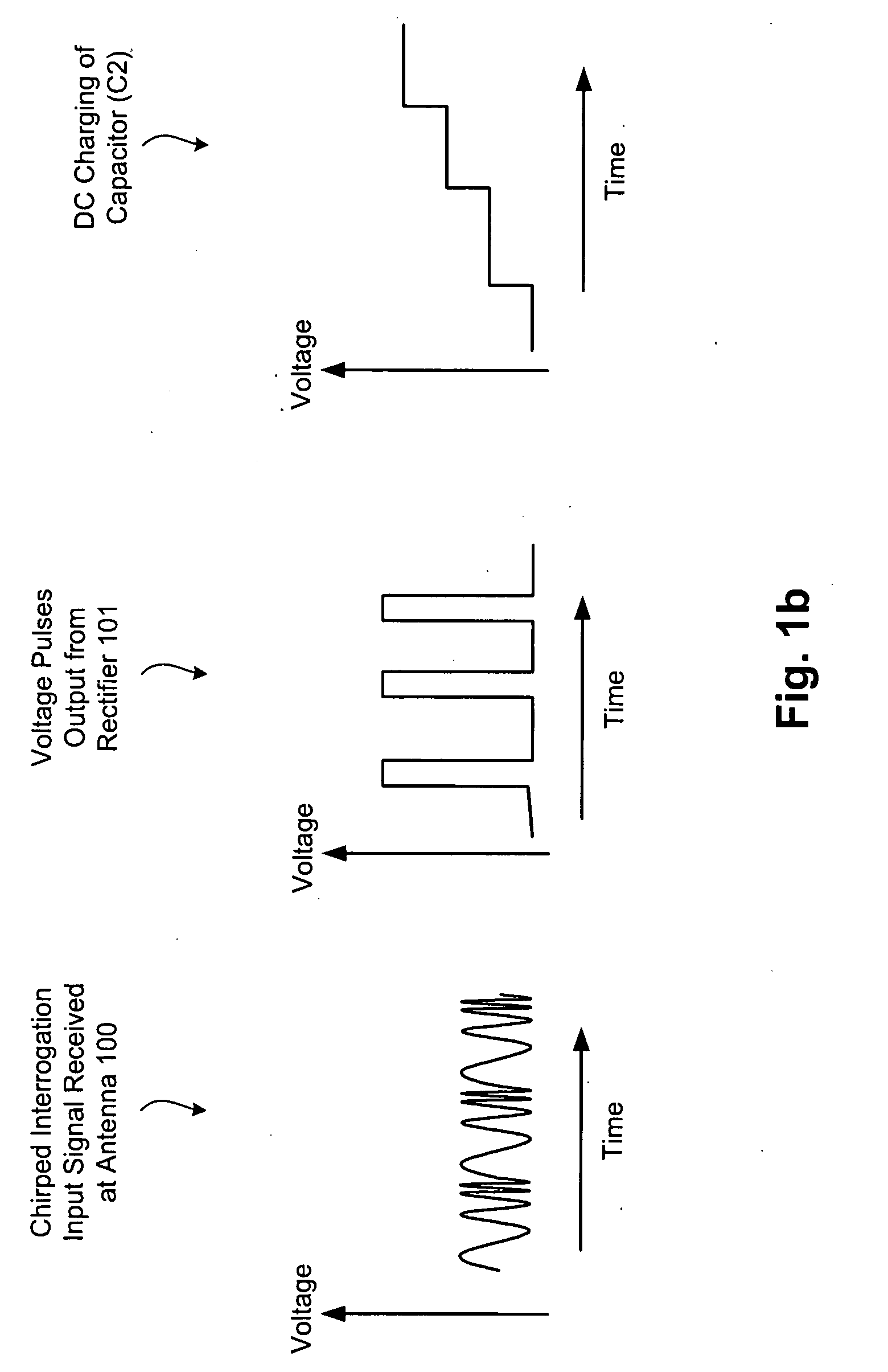
[0018]A passive RFID tag design configured in accordance with an embodiment of the present invention includes a frequency-dispersive antenna operatively coupled to a rectification circuit (sometimes collectively referred to as a rectenna), a hysteretic switch, and an RFID circuit. The rectification circuit operates to convert RF energy collected by the dispersive antenna to DC voltage, multiply that voltage, and store the resulting voltage (in a storage capacitor, which effectively acts as a battery for passive tags). The rectification circuit is configured with component values (including one or more stages of rectification diodes and filter / storage capacitors) selected depending on the frequency band of interest and the amount...


PUM


Abstract

RFID tag designs and sensors are disclosed that include a dispersive antenna and exhibit greater detection ranges relative to conventional designs. The designs include, for example a transponder having including a rectifier, a radio-frequency identification (RFID) circuit for receiving and responding to interrogation signals, and a frequency dispersion element for receiving a multi-phase input signal and creating a pulse therefrom for input to the rectifier. Frequency-dispersive elements (e.g., antennas) and compatible interrogation waveforms can be used so that the rectifying diodes receive high peak voltage levels relative to the average voltage levels.

Description

RELATED APPLICATIONS[0001]This application is a continuation-in-part to U.S. application Ser. No. 11 / 578,275, filed Jul. 30, 2007, and titled “Microradio Design, Manufacturing Method, and Applications for Use of Microradios”. In addition, application is related to U.S. application Ser. No. ______ (Attorney Docket 20050085), filed Nov. 14, 2008, and titled “Transponder with Stabilized Oscillator”. Each of these applications is herein incorporated by reference in its entirety.FIELD OF THE INVENTION[0002]The invention relates to transponders, and more particularly, to transponders designed to operate in a coherent manner.BACKGROUND OF THE INVENTION[0003]Radio-frequency identification (RFID) is an identification technique that involves the use of devices known as RFID tags. An RFID tag is a transponder that can be attached to or otherwise integrated into an item to be tracked. The item may be, for example, a product or pallet of products such as those stored in a distributor's warehouse...

Claims


Application Information

Patent Timeline
IPC IPC(8): H04Q5/22H01Q1/36
CPCG06K19/07749H01Q1/36H04Q2209/75H04Q9/00H04Q2209/47H01Q9/27
Inventor ROSSMAN, COURTAPOSTOLOS, JOHN T.BROMMER, KARL D.
Owner RADIOFIDO
Learn More