OCT Combining Probes and Integrated Systems

a technology of applied in the field of oct combining probes and integrated systems, can solve problems such as birefringence and length change, and achieve the effect of reducing noise and interference, and being easy to integrate into compact handpieces

Active Publication Date: 2009-11-19
EXCELITAS TECH
View PDF31 Cites 173 Cited by
  • Summary
  • Abstract
  • Description
  • Claims
  • Application Information

AI Technical Summary

Benefits of technology

[0006]The present invention concerns probe and OCT system designs that minimize noise and interference due to the effects of mechanical movement and strain on the OCT system. It also concerns optical designs that are robust against amplitude noise from the OCT laser source. In embodiments, this is achieved by combining the OCT signals from the reference arms and signals arms of the OCT interferometer in the handpiece itself. This combining is performed by fiber couplers that are easily integrated into compact handpieces and connected to scanning units and fiber reference arms. Thus, noise due to movement and stress to the system, such as to the umbilical that connects the analysis system to the probe, does not corrupt the OCT analysis and / or image since the noise is common and does not appear on only the reference or signal arms of the interferometer. In examples, amplitude referencing is performed and delay matched to the interference signals to compensate for the optical delay associated with the umbilical and other components. Also integrated OCT system-probes are included that yield compact and robust electro-opto-mechanical systems along with polarization sensitive OCT systems.

Problems solved by technology

Any concomitant mechanical stress on the fiber can induce length changes and birefringence due to twisting.

Method used


Image

  • OCT Combining Probes and Integrated Systems
  • OCT Combining Probes and Integrated Systems
  • OCT Combining Probes and Integrated Systems

Examples


second embodiment

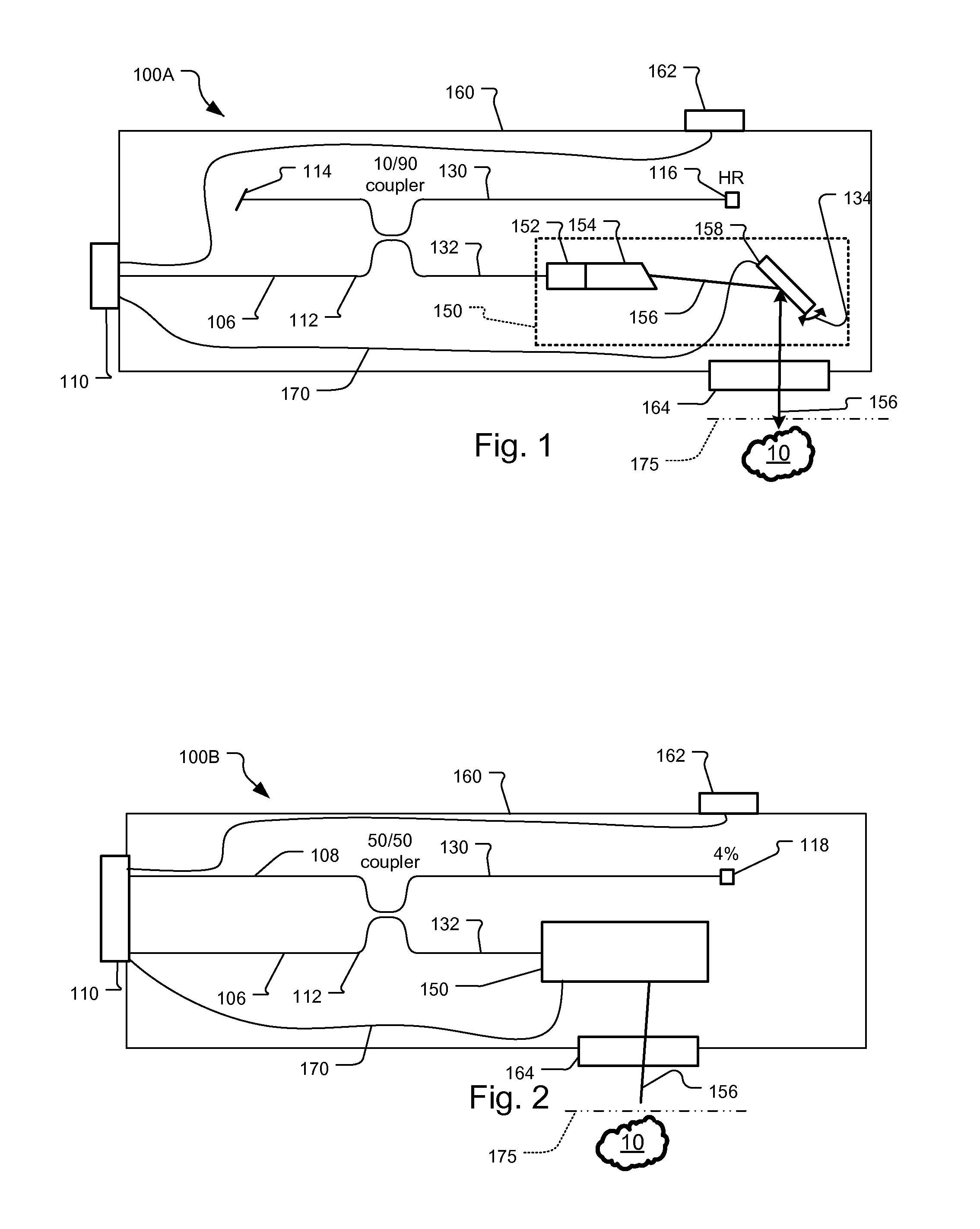
[0045]FIG. 2 shows the OCT probe 100B. This embodiment is generally similar to the first probe embodiment but uses two OCT / interference signal fibers 106, 108 to optically connect the OCT probe 100 to the OCT analysis system. This probe is compatible with standard balanced receiver / relative intensity noise (RIN) reduction scheme, and would also suppress autocorrelation artifacts from the sample signal interfering with itself.

[0046]In more detail, the OCT signal from the OCT analysis system is received via the electro-optical connector 110 typically through a flexible umbilical on a first OCT / interference signal fiber 106 and a second OCT / interference signal fiber 108, or only one of these fibers.

[0047]The light is then coupled to via a 50 / 50 interference / OCT signal coupler 112 between the reference arm optical fiber 130 and the signal arm optical fiber 132.

[0048]The OCT signal on the reference arm optical fiber is transmitted to a partial reflector 118. In one example, this partial ...

first embodiment

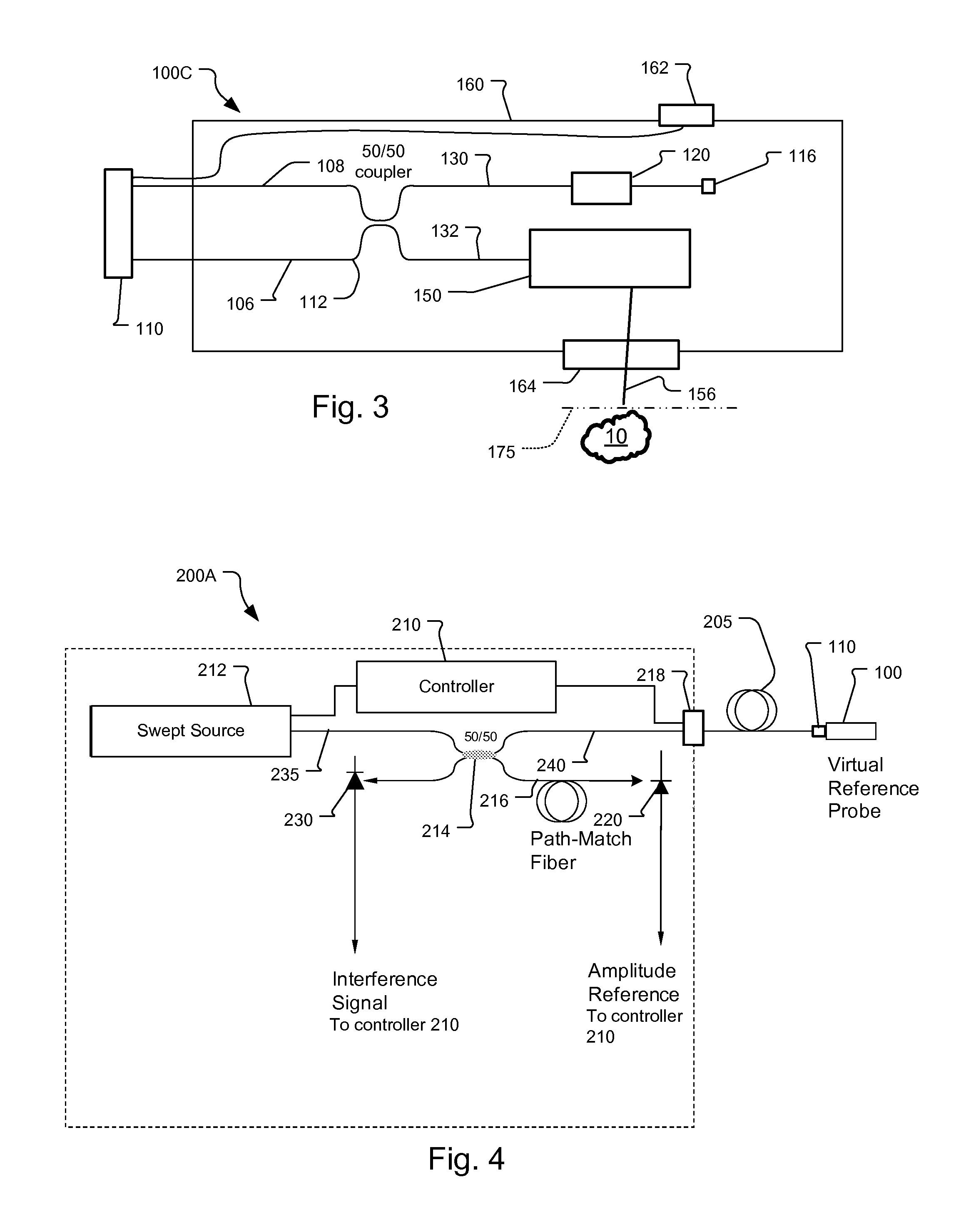
[0082]FIG. 10A shows a swept source polarization sensitive OCT system 200E that is compatible with the polarization sensitive, common path probes of FIGS. 8A and 9. In this embodiment, all of the optical fibers in the system are polarization maintaining.

[0083]In more detail, the swept source laser 212, provides a linearly polarized output aligned to the slow axis of the PM fiber of the system and specifically the PM fiber used for the swept source optical fiber 235. The OCT / amplitude reference fiber coupler 214 is similarly a PM fiber coupler that divides light between the amplitude path match fiber 216 and the OCT probe PM fiber 240. Preferably the OCT / amplitude reference fiber coupler 214 is an unbalanced coupler so that most of the OCT signal is transmitted to the sample, i.e., greater than 90% and preferably 95% or more. The OCT signal light on the OCT probe optical fiber 240 passes through interference signal circulator 242 to be transmitted to the reference probe 100 via the O...


PUM


Abstract

Optical coherence tomography (OCT) probe and system designs are disclosed that minimize the effects of mechanical movement and strain to the probe to the OCT analysis. It also concerns optical designs that are robust against noise from the OCT laser source. Also integrated OCT system-probes are included that yield compact and robust electro-opto-mechanical systems along with polarization sensitive OCT systems.

Description

RELATED APPLICATIONS[0001]This application claims the benefit under 35 USC 119(e) of U.S. Provisional Application No. 61 / 053,241, filed on May 15, 2008, which is incorporated herein by reference in its entirety.BACKGROUND OF THE INVENTION[0002]Optical coherence analysis relies on the use of the interference phenomena between a reference wave and an experimental wave or between two parts of an experimental wave to measure distances and thicknesses, and calculate indices of refraction of an object of interest. Optical Coherence Tomography (OCT) is one example technology that is used to perform usually high-resolution cross sectional imaging that can provide images of objects such as biological tissue structures, for example, on the microscopic scales in real time. Optical waves are sent through an object and a computer produces images of cross sections of the object by using information on how the waves are changed.[0003]The original OCT imaging technique is the time-domain OCT (TD-OC...

Claims


Application Information

Patent Timeline
Patent Type & Authority Applications(United States)
IPC IPC(8): G01B11/02
CPCA61B5/0066A61B5/0073G01N21/4795G01B2290/70G01B9/02057G01B9/0205G01B9/02091G01B9/02004
Inventor JOHNSON, BARTLEY C.FLANDERS, DALE C.
Owner EXCELITAS TECH
Why Eureka
Try Eureka