Radio quality degradation prediction system, wireless terminal and monitoring server therefor, radio quality degradation prediction method and program

Inactive Publication Date: 2009-11-19
NEC CORP
View PDF14 Cites 32 Cited by
  • Summary
  • Abstract
  • Description
  • Claims
  • Application Information

AI Technical Summary

Benefits of technology

[0027]According to certain embodiments of the present invention, degradation of radio quality at a future position of a wireless terminal can be predicted sufficiently in advance and with accuracy. This is because movement characteristics of human beings are easy to predict because they do not change the speed or direction of their movement suddenly as compared to prediction of a complex radiowave propagation environment in an urban area. Also, this is because it is possible to estimate a complex radiowave propagation environment with a high degree of accuracy, by using a radiowave propagation simulator based on a ray trac

Problems solved by technology

In wireless communication, communication quality significantly degrades in some locations (i.e., dead zones) due to blockage of radiowave by a building or terrain, influence of multi-path interference or the like.
In many wireless communication systems for mobile phones or the like, some dead zones remain even after area development is completed because of the huge cost required to decrease the number of dead zones to near zero.
Since the existence of such dead zones is presupposed, however, utilization of wireless communication as a reliable means of communication is hampered.
However, there is no effective solution for the problem of radio dead zones, and typically communication quality sudden

Method used


Image

  • Radio quality degradation prediction system, wireless terminal and monitoring server therefor, radio quality degradation prediction method and program
  • Radio quality degradation prediction system, wireless terminal and monitoring server therefor, radio quality degradation prediction method and program
  • Radio quality degradation prediction system, wireless terminal and monitoring server therefor, radio quality degradation prediction method and program

Examples


second embodiment

[0049]In FIG. 3, the radio quality degradation prediction system according to the present invention includes a wireless terminal 11 and a monitoring server 21. The wireless terminal 11 and the monitoring server 21 perform wireless communication with each other via the wireless network 30.

[0050]In FIG. 3, the monitoring server 21 has the radio propagation prediction unit 201, and transmits a result of estimating radiowave propagation in the vicinity of an area, in which the wireless terminal 11 is present, to the wireless terminal 11 via the wireless network 30.

first embodiment

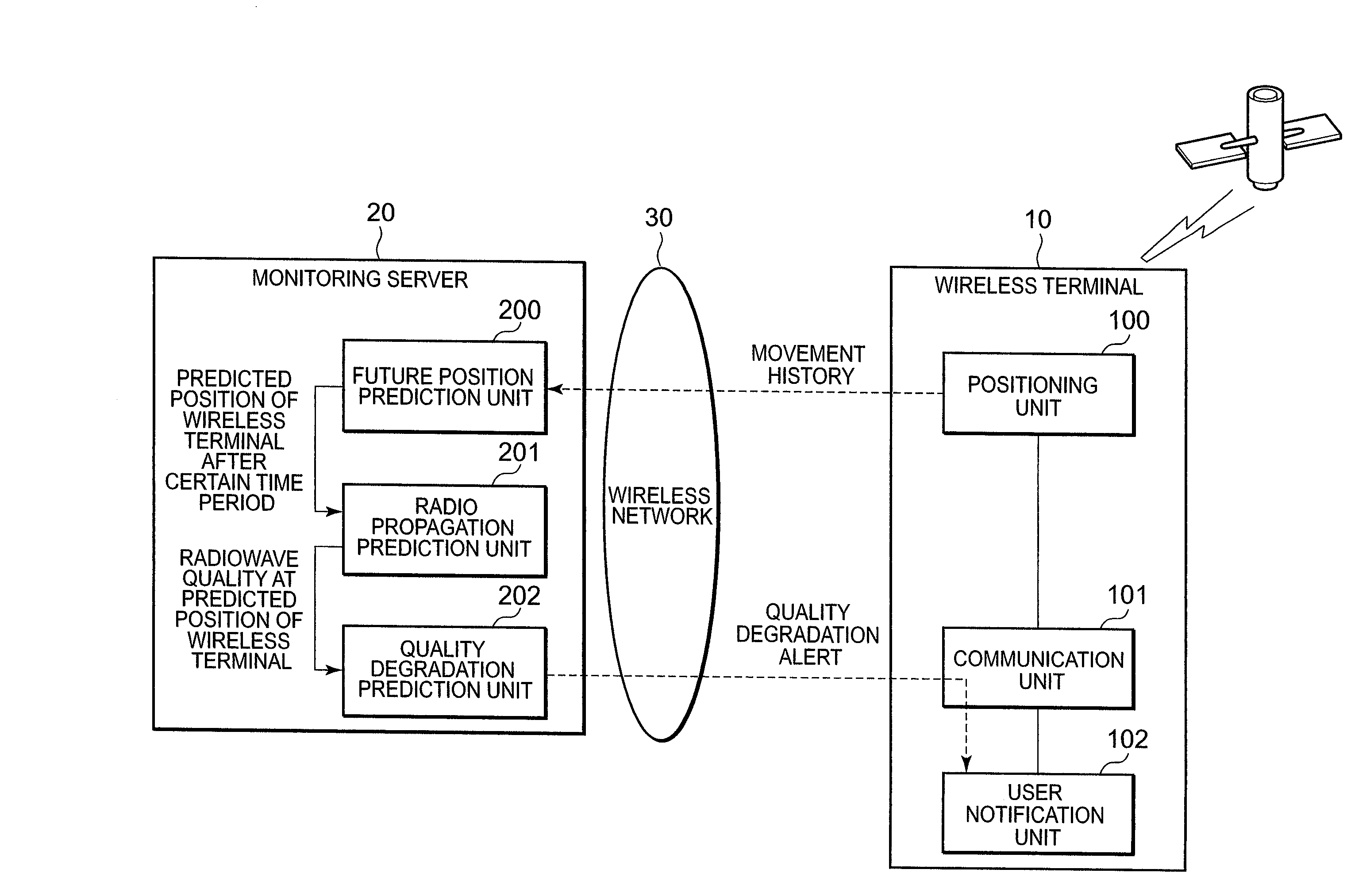
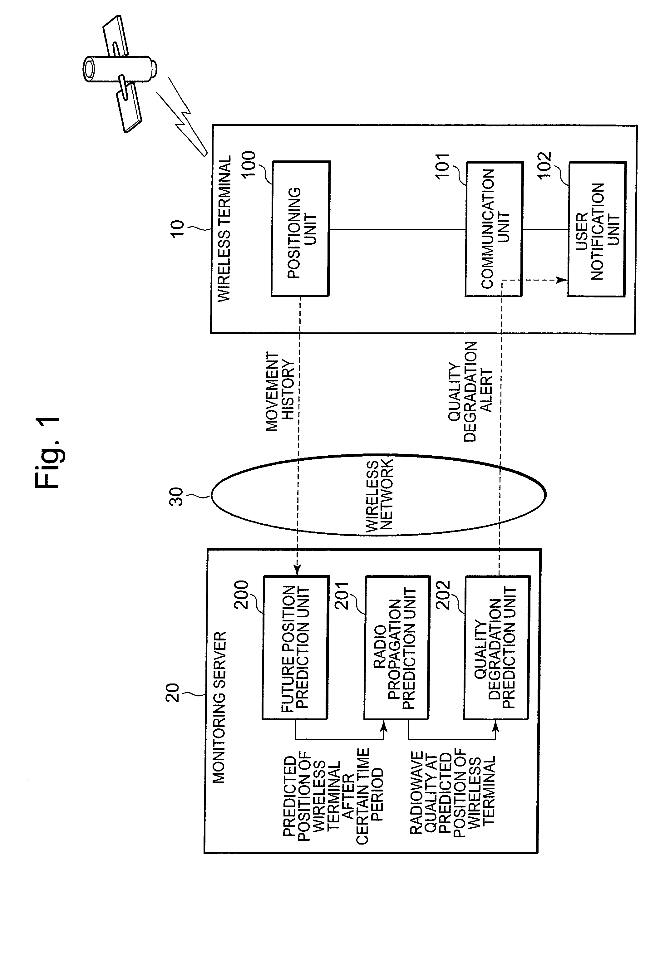
[0051]On the other hand, the future position prediction unit and the quality degradation prediction unit, which are provided in the monitoring server 20 in FIG. 1 that shows the configuration of the radio quality degradation prediction system according to the present invention, are provided as a future position prediction unit 103 and a quality degradation prediction unit 105 in the wireless terminal 11. That is, the functions of the future position prediction unit and the quality degradation prediction unit of the monitoring server 20 in FIG. 1 have been transferred to the wireless terminal 11 side.

[0052]In addition, the wireless terminal 11 includes a radio propagation prediction result maintaining unit 104 that accumulates results of estimating radiowave propagation in the vicinity of an area in which the wireless terminal 11 is present. The positioning unit 100, communication unit 101, and user notification unit 102 are provided as in the wireless terminal 10 of the first embodi...

third embodiment

[0060]In the present invention, the future position prediction unit 200 of the monitoring server 22 receives movement histories of the wireless terminals 12, 13 and 14 at a particular time, and the radio propagation prediction unit 201 of the monitoring server 22 estimates a range within which a wireless signal of a multi-hop network can reach based on the terminals' future positions.

[0061]According to the third embodiment of the invention, therefore, service area quality in a multi-hop network at a future point in time can be estimated and an alert on quality degradation can be issued to the individual wireless terminals even though a service area changes in accordance with the position of a plurality of wireless terminals.

[0062]The processing operation of the radio quality degradation prediction system according to the embodiments of the present invention can be realized by causing a computer having a CPU and serving as a control unit, to read and execute a program stored in a sto...


PUM


Abstract

A radio quality degradation prediction system includes a wireless terminal and a monitoring server. The wireless terminal includes a positioning unit that determines a position of the wireless terminal and notifies the monitoring server of movement history of the wireless terminal via a wireless network, and a user notification unit that gives a warning to a user upon receiving a radio quality degradation alert at the wireless terminal. The monitoring server includes a future position prediction unit that predicts a future position of the wireless terminal based on the movement history of the wireless terminal, a radio propagation prediction unit that estimates radio quality in a service coverage area by using a radiowave propagation simulator, and a quality degradation prediction unit that predicts degradation of radio quality at the future position of the wireless terminal and transmits a radio quality degradation alert to the wireless terminal.

Description

[0001]This application is based upon and claims the benefit of priority from Japanese patent application No. 2008-128318, filed on May 15, 2008, the disclosure of which is incorporated in its entirety by reference.TECHNICAL FIELD[0002]Aspects of the present invention relate to management of communication quality in a wireless communication terminal, and more specifically, to a radio quality degradation prediction system, wireless terminal and monitoring server therefor, and a radio quality degradation prediction method and program that predicts degradation of quality based on radiowave propagation problems.DESCRIPTION OF THE RELATED ART[0003]In wireless communication, communication quality significantly degrades in some locations (i.e., dead zones) due to blockage of radiowave by a building or terrain, influence of multi-path interference or the like. In many wireless communication systems for mobile phones or the like, some dead zones remain even after area development is completed...

Claims


Application Information

Patent Timeline
IPC IPC(8): H04M11/00H04L12/26H04W24/00
CPCG01S2205/007H04W64/00H04W24/00H04L43/0847
Inventor MATSUNAGA, YASUHIKO
Owner NEC CORP
Why Eureka
Try Eureka