Method for minimally invasive medical intervention

a medical intervention and minimally invasive technology, applied in the field of medical intervention for patients, can solve the problems of inability to obtain data using conventional ct or mri imaging with intravenous injection, damage to the unintended area of heated blood, and decrease the effectiveness of ablating tissu

Inactive Publication Date: 2009-11-19
SIEMENS AG
View PDF12 Cites 19 Cited by
  • Summary
  • Abstract
  • Description
  • Claims
  • Application Information

AI Technical Summary

Benefits of technology

[0012]The present invention provides a process as a workflow for a minimally invasive intervention. In particular, a method is provided as a clinical workflow for minimally invasive medical interventions using a an x-ray imaging system, wherein real-time images obtained by a low dose imaging apparatus, for example a fluoroscopic imaging system, of an afflicted area of the patient as obtained during an interventional procedure are used along with high dose images, such as computed tomography images, angiographic images and/or functional images of the afflicted area obtained prior to or following the intervention, or both, without moving the patient from the imaging suite. The patient is positioned at the x-ray imaging apparatus so that the intervention can be performed while using the low dose, real time imaging capability of the imaging apparatus. High dose, pre-interventional images can be obtained of the patient's anatomy while the patient is in position at the imaging apparatus, if desired. Following the intervention, h

Problems solved by technology

The loss of heat as a result of the blood flow not only decreases the effectiveness of ablating tissue in the area of interest but also may result in damage to unintended area to which the heated blood is carried.
Some of this data cannot be obtained using conventional CT or MRI imaging with intravenous contrast injection, but require imaging with selective i

Method used


Image

  • Method for minimally invasive medical intervention
  • Method for minimally invasive medical intervention
  • Method for minimally invasive medical intervention

Examples


Embodiment Construction

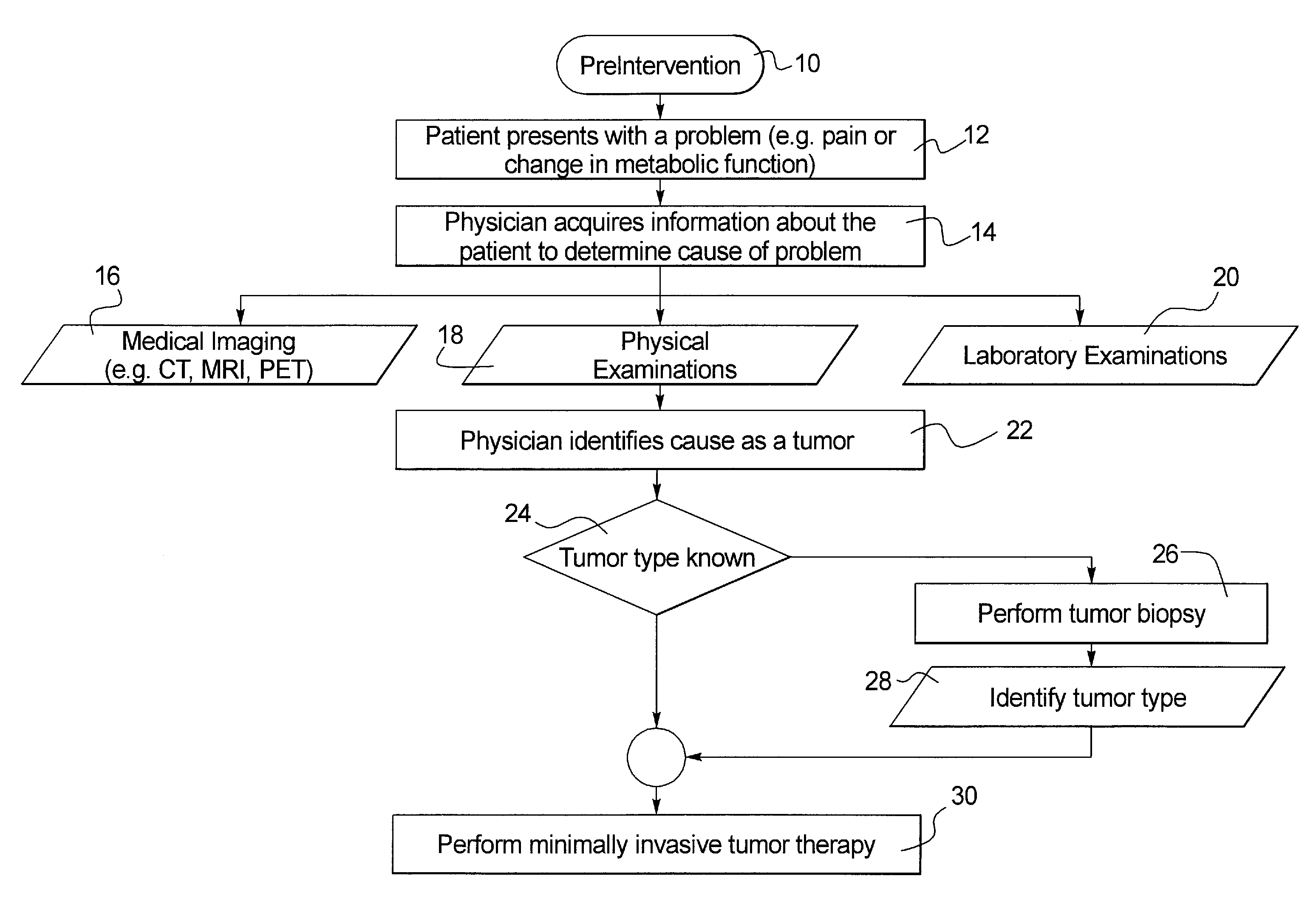
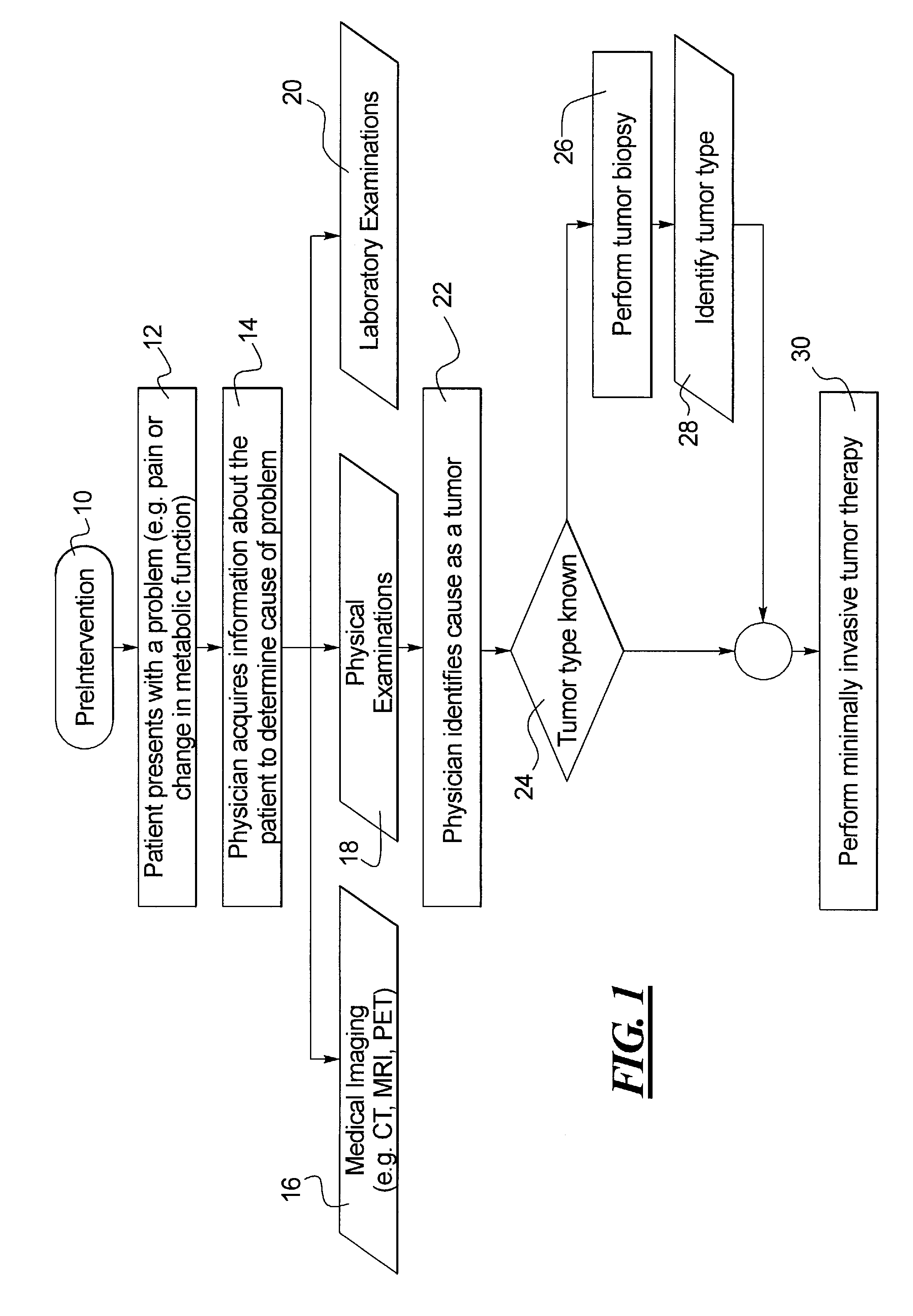
[0016]In FIG. 1, workflow process is performed for a patient who in this example is suspected of having a tumor. In the first step, a pre-intervention is begun at 10. The patient presents with a problem, such as a pain or a change in a metabolic function, at step 12. In step 14, the physician acquires information about the patient to determine the cause of the problem. The acquisition of information may include any or all of the steps of performing a medical imaging, such as a CT (computer tomography) imaging, an MRI (magnetic resonance imaging), or a PET (positron emission tomography) imaging, as shown at 16, a physical examination of the patient, at 18, and laboratory examinations or tests, at 20. Any images acquired in this pre-intervention phase are preferably stored for later reference.

[0017]After completing one or more of these investigations, the physician identifies the cause as a tumor, at step 22. At 24, a decision is made as to whether the tumor type is known. If not, a t...


PUM


Abstract

A workflow for a minimally invasive intervention, such as a treatment for a cancerous tumor, includes positioning a patient at a multi-functional imaging apparatus, obtaining pre-interventional images of the anatomy of the patient using a computed tomography or angiography imaging function, performing the minimally invasive intervention while the patient is positioned at the multi-functional imaging apparatus and while using a fluoroscopic imaging function, and performing a post-interventional imaging of the patient's anatomy while the patient is positioned at the multi-functional imaging apparatus using the computed tomography or angiographic imaging function. If the post-interventional imaging determines that additional intervention is in order, the additional intervention is performed while the patient is positioned at the imaging apparatus. Pre-intervention images and data sets from other sources may be combined with or used during the intervention. A treatment planning step may be included following the pre-interventional imaging and the intervention.

Description

BACKGROUND OF THE INVENTION[0001]1. Field of the Invention[0002]The present invention relates generally to a method for medical intervention for a patient, and more specifically to a method or process as a clinical workflow for minimally invasive therapy utilizing medical imaging of the afflicted area of the patient.[0003]2. Description of the Related Art[0004]Patients who are suspected of having cancer or who have cancerous diseases are increasingly being treated with minimally invasive procedures. The minimally invasive procedures may be performed by interventional radiologists using a percutaneous approach. In the percutaneous approach, a miniature device is inserted into blood vessels or different organ systems, such as the liver, spleen or kidney, through a small opening in the skin and this device is directed to the site of the cancer.[0005]Diagnosis of cancerous diseases may be provided by obtaining a diagnostic biopsy, wherein a sample of tissue from the suspect tissue is ob...

Claims


Application Information

Patent Timeline
IPC IPC(8): A61B5/00
CPCA61B6/4441A61B6/504A61B6/481
Inventor MEISSNER, OLIVERRAUCH, JOHN CHRISTOPHERREDEL, THOMASZELLERHOFF, MICHAEL
Owner SIEMENS AG
Why Eureka
Try Eureka